
Owner's manual
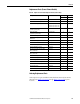
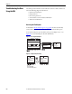
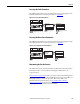
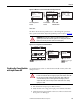
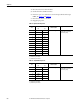
Table Of Contents
- Front Cover
- Important User Information
- Summary of Changes
- Table of Contents
- Introduction
- About the Drive
- Identifying the Drive by Cabinet Assembly ID Number
- LiquiFlo 2.0 Drive Component Locations
- Identifying the Power Module by Model Number
- AC Line I/O Board Description (Frame 3 Only)
- Standard I/O Board Description (Frame 3 Only)
- Combined I/O Board Description (Frame 4 Only)
- DPI Communication Ports
- Optional Equipment
- Planning the Installation
- Mounting The Power Module and Grounding the Drive
- Installing Input and Output Power Wiring
- Completing the Installation
- Using the Start-up Routines
- Programming Basics
- Parameter Descriptions
- Troubleshooting the Drive
- Verify that the DC Bus Capacitors are Discharged Before Servicing the Drive
- Determining Drive Status Using the Status LEDs
- About Alarms
- About Faults
- Diagnostic Parameters
- Common Symptoms and Corrective Actions
- Replacement Parts
- Board Replacement, Firmware Setup Procedures
- Troubleshooting the Drive Using the OIM
- Checking the Power Modules with Input Power Off
- Technical Specifications
- Using the OIM
- Installing and Removing the OIM
- Display Description
- OIM Menu Structure
- Powering Up and Adjusting the OIM
- Selecting a Device in the System
- Using the OIM to Program the Drive
- Monitoring the Drive Using the Process Display Screen on the OIM
- Displaying and Changing the OIM Reference
- Customizing the Process Display Screen
- Customizing the Function Keys
- Controlling the Drive From the OIM
- LiquiFlo 2.0 Drive Frame 3 Wiring Diagrams
- LiquiFlo 2.0 Drive Frame 4 Wiring Diagrams
- Index
- Back Cover

230 Rockwell Automation Publication D2-3518-3 - May 2013
Chapter 10
4. Disconnect the motor from the drive.
5. Check all AC line and DC bus fuses.
6. If a fuse is open, use a multimeter to check the input diodes and output
IGBTs. See Tab le 3 5
and Ta b le 36 .
7. Reconnect the motor to the drive.
8. Reapply input power.
Table 35 - Input Diode Components
* (+) DC Bus Volts power terminal
** (-) DC Bus Volts power terminal
Table 36 - Output IGBT Components
* (+) DC Bus Volts power terminal
** (-) DC Bus Volts power terminal
Input Diode
No.
Meter Connection Component is OK if
resistance (R) is:
Component is defective if:
(+) (–)
1 * L1 10 < R < 1 megohm Continuity (short circuit) or open
when the meter is connected
with reversed polarity.
2*L2
3*L3
4*L4
5*L5
6*L6
7L1**
8L2**
9L3**
10 L4 **
11 L5 **
12 L6 **
Output IBGT
No.
Meter Connection Component is OK if
resistance (R) is:
Component is defective if:
(+) (–)
1 * W/T3 10 < R < 1 megohm Continuity (short circuit) or open
when the meter is connected
with reversed polarity.
2 * V/T2
3*U/T1
4W/T3**
5 V/T2 **
6U/T1**