
Owner's manual
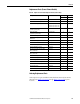
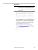
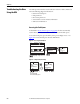
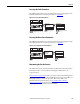
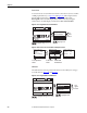
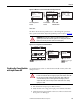
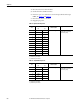
Table Of Contents
- Front Cover
- Important User Information
- Summary of Changes
- Table of Contents
- Introduction
- About the Drive
- Identifying the Drive by Cabinet Assembly ID Number
- LiquiFlo 2.0 Drive Component Locations
- Identifying the Power Module by Model Number
- AC Line I/O Board Description (Frame 3 Only)
- Standard I/O Board Description (Frame 3 Only)
- Combined I/O Board Description (Frame 4 Only)
- DPI Communication Ports
- Optional Equipment
- Planning the Installation
- Mounting The Power Module and Grounding the Drive
- Installing Input and Output Power Wiring
- Completing the Installation
- Using the Start-up Routines
- Programming Basics
- Parameter Descriptions
- Troubleshooting the Drive
- Verify that the DC Bus Capacitors are Discharged Before Servicing the Drive
- Determining Drive Status Using the Status LEDs
- About Alarms
- About Faults
- Diagnostic Parameters
- Common Symptoms and Corrective Actions
- Replacement Parts
- Board Replacement, Firmware Setup Procedures
- Troubleshooting the Drive Using the OIM
- Checking the Power Modules with Input Power Off
- Technical Specifications
- Using the OIM
- Installing and Removing the OIM
- Display Description
- OIM Menu Structure
- Powering Up and Adjusting the OIM
- Selecting a Device in the System
- Using the OIM to Program the Drive
- Monitoring the Drive Using the Process Display Screen on the OIM
- Displaying and Changing the OIM Reference
- Customizing the Process Display Screen
- Customizing the Function Keys
- Controlling the Drive From the OIM
- LiquiFlo 2.0 Drive Frame 3 Wiring Diagrams
- LiquiFlo 2.0 Drive Frame 4 Wiring Diagrams
- Index
- Back Cover
Rockwell Automation Publication D2-3518-3 - May 2013 229
Chapter 10
Figure 89 - OIM Version Screens at the Product and Component Levels
Device Items
The Device Items selection provides access to a list of diagnostic parameters.
These parameters should be adjusted by qualified personnel only. See Figure 90
.
Figure 90 - Accessing the Device Item Information
Checking the Power Modules
with Input Power Off
Use the following procedure to check the Power Module circuitry of the drive
with power off.
1. Turn off and lock out input power. Wait 5 minutes.
2. Verify that there is no voltage at the input power terminals of the drive.
3. Check the DC bus potential with a voltmeter to make sure that the DC
bus capacitors are discharged.
ATTENTION: The parameters in the Device Items menu must be set by a
qualified person who understands the significance of setting them accurately.
Failure to observe this precaution could result in bodily injury.
Diag: Prodct Ver
Date: mm/dd/yyyy
FW Ver: x.xxx
Series: X
Cmp
F1
F1
Diag: OIM Comp
Prev
LCD OIM Standard
Control Board
Prdt
Next
Flash
To Component
Level
To Product
Level
F1 F3
Flash F/W
Information
Diag: Comp Ver
FW Ver: x.xxx
HW Ver: xxx
S#: xxxxxxxx
Diagnostics
:
Device Items
Fault Info
Monitor Lang
P0: LiquiFlo 2.0
Stopped Auto
Main Menu
Diagnostics
Status Infor
Highlight Diagnostics icon
Highlight item
Dev Item #
Param name
Param value
Dflt
Scroll through
items
F1
Display default
>>
ATTENTION: DC bus capacitors retain hazardous voltages after input power has
been disconnected. After disconnecting input power, wait 5 minutes for the DC
bus capacitors to discharge and then check the voltage with a voltmeter to
ensure the DC bus capacitors are discharged before touching any internal
components. Failure to observe this precaution could result in severe bodily
injury or loss of life.