
Owner's manual
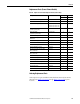
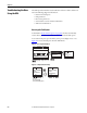
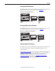
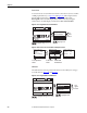
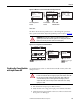
Table Of Contents
- Front Cover
- Important User Information
- Summary of Changes
- Table of Contents
- Introduction
- About the Drive
- Identifying the Drive by Cabinet Assembly ID Number
- LiquiFlo 2.0 Drive Component Locations
- Identifying the Power Module by Model Number
- AC Line I/O Board Description (Frame 3 Only)
- Standard I/O Board Description (Frame 3 Only)
- Combined I/O Board Description (Frame 4 Only)
- DPI Communication Ports
- Optional Equipment
- Planning the Installation
- Mounting The Power Module and Grounding the Drive
- Installing Input and Output Power Wiring
- Completing the Installation
- Using the Start-up Routines
- Programming Basics
- Parameter Descriptions
- Troubleshooting the Drive
- Verify that the DC Bus Capacitors are Discharged Before Servicing the Drive
- Determining Drive Status Using the Status LEDs
- About Alarms
- About Faults
- Diagnostic Parameters
- Common Symptoms and Corrective Actions
- Replacement Parts
- Board Replacement, Firmware Setup Procedures
- Troubleshooting the Drive Using the OIM
- Checking the Power Modules with Input Power Off
- Technical Specifications
- Using the OIM
- Installing and Removing the OIM
- Display Description
- OIM Menu Structure
- Powering Up and Adjusting the OIM
- Selecting a Device in the System
- Using the OIM to Program the Drive
- Monitoring the Drive Using the Process Display Screen on the OIM
- Displaying and Changing the OIM Reference
- Customizing the Process Display Screen
- Customizing the Function Keys
- Controlling the Drive From the OIM
- LiquiFlo 2.0 Drive Frame 3 Wiring Diagrams
- LiquiFlo 2.0 Drive Frame 4 Wiring Diagrams
- Index
- Back Cover

Rockwell Automation Publication D2-3518-3 - May 2013 225
Chapter 10
Combined Power Board
1. Verify that power board inverter data is correct by checking inverter read-
only parameter 28 (Rated Amps) against correct drive output current
rating.
2. Verify that power board rectifier data is correct by checking rectifier read-
only parameter 28 (Rated Amps) against correct rectifier output current
rating
3. Reset all inverter parameters to defaults by setting inverter parameter 197
(Reset to Defalts) to 1. The value of parameter 197 (Reset to Defalts)
returns to 0 immediately after 1 is written to memory. This action should
clear faults 100 (Parameter Checksum) and 107 (Replaced MCB-PB).
4. Reset all rectifier parameters to defaults by setting rectifier parameter 197
(Reset to Defalts) to 1. The value of parameter 197 (Reset to Defalts)
returns to 0 immediately after 1 is written to memory.
5. If drive is still faulted, attempt to reset the fault using the normal
procedure. See Clearing Drive Faults
on page 222. If drive is still faulted
after this attempt is made, troubleshoot on the basis of the current fault.
6. Reprogram all drive parameters.
Standard I/O Board Connections
Mount the Standard I/O Board on the Power Module with hardware provided.
IMPORTANT
If drive fault 106 (Incompat MCB-PB) or fault 235 (Rctfr Pwr Board) occurs after
replacing board or at any other point during this procedure, then the new
combined power board is incompatible with the old combined control board,
or the data stored on the old combined control board has become corrupt.
Replace the old combined control board. If the fault still exists, replace the new
combined power board.