
Owner's manual
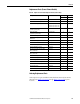
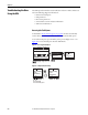
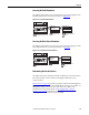
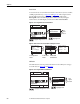
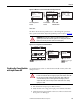
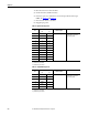
Table Of Contents
- Front Cover
- Important User Information
- Summary of Changes
- Table of Contents
- Introduction
- About the Drive
- Identifying the Drive by Cabinet Assembly ID Number
- LiquiFlo 2.0 Drive Component Locations
- Identifying the Power Module by Model Number
- AC Line I/O Board Description (Frame 3 Only)
- Standard I/O Board Description (Frame 3 Only)
- Combined I/O Board Description (Frame 4 Only)
- DPI Communication Ports
- Optional Equipment
- Planning the Installation
- Mounting The Power Module and Grounding the Drive
- Installing Input and Output Power Wiring
- Completing the Installation
- Using the Start-up Routines
- Programming Basics
- Parameter Descriptions
- Troubleshooting the Drive
- Verify that the DC Bus Capacitors are Discharged Before Servicing the Drive
- Determining Drive Status Using the Status LEDs
- About Alarms
- About Faults
- Diagnostic Parameters
- Common Symptoms and Corrective Actions
- Replacement Parts
- Board Replacement, Firmware Setup Procedures
- Troubleshooting the Drive Using the OIM
- Checking the Power Modules with Input Power Off
- Technical Specifications
- Using the OIM
- Installing and Removing the OIM
- Display Description
- OIM Menu Structure
- Powering Up and Adjusting the OIM
- Selecting a Device in the System
- Using the OIM to Program the Drive
- Monitoring the Drive Using the Process Display Screen on the OIM
- Displaying and Changing the OIM Reference
- Customizing the Process Display Screen
- Customizing the Function Keys
- Controlling the Drive From the OIM
- LiquiFlo 2.0 Drive Frame 3 Wiring Diagrams
- LiquiFlo 2.0 Drive Frame 4 Wiring Diagrams
- Index
- Back Cover

Rockwell Automation Publication D2-3518-3 - May 2013 221
Chapter 10
Replacement Parts (Frame 4 Power Module)
Table 34 - LiquiFlo 2.0 Power Module Replacement Parts (Frame 4 Only)
Ordering Replacement Parts
Order replacement parts available from Rockwell Automation by kit number,
when listed. See Figure 2 on page 15
through Figure 7 on page 22 for parts
locations.
Description Part Number / Kit Number Quantity Quantity
LF200900CCR LF201215CCR
Combined Power PCB Assembly, 900 A 21T-316972-A02 1 -
Combined Power PCB Assembly, 1215 A 21T-316972-A01 - 1
Wire Harness Assembly, Gate Driver 181565-C04 (L1 - two of each)
181565-C05 (L2 - two of each)
181565-C06 (L3 - two of each)
22
Internal Fan, 24V DC
(internal to power module)
21T-181775-A02 1 1
Internal Fan, 24V DC
(on bottom of power module)
21T-181775-A03 2 2
Wire Harness Assembly, Internal Fan 180316-Q01 1 1
Wire Harness Assembly, Gate Driver,
Rectifier Side
180427-Q01 1 1
Wire Harness Assembly, DC Power 180427-Q02 1 1
Current Feedback Device, 1000 A 180307-Q01 1 1
Wire Harness Assembly, DC Bus Resistors 180315-Q02 1 1
Current Feedback Device, 2000 A 179757-Q01 6 6
Wire Harness Assembly, Current Feedback
Device, Rectifier Side
181566-C03 1 1
Wire Harness Assembly, Current Feedback
Device, Inverter Side
181566-C04 1 1
Wire Harness Assembly, RTD, Rectifier Side 181567-C03 1 1
Wire Harness Assembly, RTD, Inverter Side 181567-C04 1 1
Cable Assembly, 40-pin 179828-Q01 2 2
Combined Control PCB Assembly 21T-180325-A01 1 1
Combined I/O PCB Assembly 21T-180370-A01 1 1
Cable Assembly, 20-pin 194706-Q01 1 1
Cable, Mini DIN, 8-position, Male/Male 180513-Q01 1 1