
Owner's manual
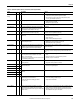
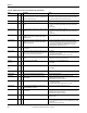
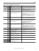
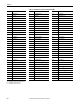
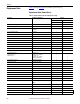
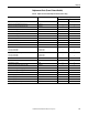
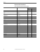
Table Of Contents
- Front Cover
- Important User Information
- Summary of Changes
- Table of Contents
- Introduction
- About the Drive
- Identifying the Drive by Cabinet Assembly ID Number
- LiquiFlo 2.0 Drive Component Locations
- Identifying the Power Module by Model Number
- AC Line I/O Board Description (Frame 3 Only)
- Standard I/O Board Description (Frame 3 Only)
- Combined I/O Board Description (Frame 4 Only)
- DPI Communication Ports
- Optional Equipment
- Planning the Installation
- Mounting The Power Module and Grounding the Drive
- Installing Input and Output Power Wiring
- Completing the Installation
- Using the Start-up Routines
- Programming Basics
- Parameter Descriptions
- Troubleshooting the Drive
- Verify that the DC Bus Capacitors are Discharged Before Servicing the Drive
- Determining Drive Status Using the Status LEDs
- About Alarms
- About Faults
- Diagnostic Parameters
- Common Symptoms and Corrective Actions
- Replacement Parts
- Board Replacement, Firmware Setup Procedures
- Troubleshooting the Drive Using the OIM
- Checking the Power Modules with Input Power Off
- Technical Specifications
- Using the OIM
- Installing and Removing the OIM
- Display Description
- OIM Menu Structure
- Powering Up and Adjusting the OIM
- Selecting a Device in the System
- Using the OIM to Program the Drive
- Monitoring the Drive Using the Process Display Screen on the OIM
- Displaying and Changing the OIM Reference
- Customizing the Process Display Screen
- Customizing the Function Keys
- Controlling the Drive From the OIM
- LiquiFlo 2.0 Drive Frame 3 Wiring Diagrams
- LiquiFlo 2.0 Drive Frame 4 Wiring Diagrams
- Index
- Back Cover

220 Rockwell Automation Publication D2-3518-3 - May 2013
Chapter 10
Replacement Parts (Frame 4 Drive)
Table 33 - LiquiFlo 2.0 Drive Replacement Parts (Frame 4 Only)
Description Part Number / Kit Number Quantity
Frame 4CC Frame 4CC
180580-A07 180580-A09
AC Contactor - 300 A, 120 V 100-D300ED11 3 3
Capacitor Bank Assembly,
1215 A
905 A
21T-LCL-CB10
21T-LCL-CB11
-
1
1
-
Circuit Breaker, Control, 15 A, 3 ph (Qty 1)
65kAIC (base drive = 1)
100kAIC (option = O)
21T-380127-A03
21T-380127-A09
1
O
1
O
Fuse Block, 30 A, 600 V, Class CC, 3-Line 117719 2 2
Fuse Block, 30 A, 600 V, Class CC, 2-Line 49454-19B 1 1
Lug, 2-600 MCM, Ground Thomas & Betts # ADR60-22D 1 1
115 V Fan SK-L1-FAN3-F3 4 4
Transformer, 5 kVA, Multi-tap 21T-MISC-B-TR1 1 1
Precharge Resistor, 47 Ohm, 300W 21T-322542-A02 (set of 3 resistors) 6 6
Circuit Breaker, Main,1500 A (Qty 1)
65kAIC (base drive = 1)
100kAIC (option = O)
21T-380127-A03
21T-380127-A08
1
O
1
O
Circuit Breaker Handle and Shaft 21T-CB-A1500-HDL 1 1
Fuse, Class CC, 600 V, 1 A Gould/Shawmut # ATQR1 3 3
Fuse, Class CC, 600 V, 10 A Gould/Shawmut # ATQR10 1 1
Fuse, Class CC, 600 V, 20 A Gould/Shawmut # ATDR20 4 4
Terminal Block, 4-Position 49455-93C 1 1
Terminal Block, 10-Position 49455-93J 2 2
900 A Power Module 21T-LF200900CCR 1 -
1215 A Power Module 21T-LF201215CCR - 1
Inductor, 905 A 21T-380097-A05 1 -
Inductor, 1215 A 21T-380097-A06 - 1
Surge Suppressor 21T-385253-A01 1 1