
Owner's manual
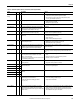
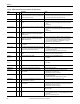
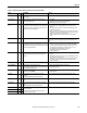
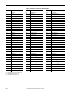
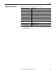
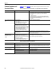
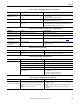
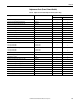
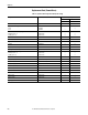
Table Of Contents
- Front Cover
- Important User Information
- Summary of Changes
- Table of Contents
- Introduction
- About the Drive
- Identifying the Drive by Cabinet Assembly ID Number
- LiquiFlo 2.0 Drive Component Locations
- Identifying the Power Module by Model Number
- AC Line I/O Board Description (Frame 3 Only)
- Standard I/O Board Description (Frame 3 Only)
- Combined I/O Board Description (Frame 4 Only)
- DPI Communication Ports
- Optional Equipment
- Planning the Installation
- Mounting The Power Module and Grounding the Drive
- Installing Input and Output Power Wiring
- Completing the Installation
- Using the Start-up Routines
- Programming Basics
- Parameter Descriptions
- Troubleshooting the Drive
- Verify that the DC Bus Capacitors are Discharged Before Servicing the Drive
- Determining Drive Status Using the Status LEDs
- About Alarms
- About Faults
- Diagnostic Parameters
- Common Symptoms and Corrective Actions
- Replacement Parts
- Board Replacement, Firmware Setup Procedures
- Troubleshooting the Drive Using the OIM
- Checking the Power Modules with Input Power Off
- Technical Specifications
- Using the OIM
- Installing and Removing the OIM
- Display Description
- OIM Menu Structure
- Powering Up and Adjusting the OIM
- Selecting a Device in the System
- Using the OIM to Program the Drive
- Monitoring the Drive Using the Process Display Screen on the OIM
- Displaying and Changing the OIM Reference
- Customizing the Process Display Screen
- Customizing the Function Keys
- Controlling the Drive From the OIM
- LiquiFlo 2.0 Drive Frame 3 Wiring Diagrams
- LiquiFlo 2.0 Drive Frame 4 Wiring Diagrams
- Index
- Back Cover

Rockwell Automation Publication D2-3518-3 - May 2013 219
Chapter 10
Replacement Parts (Frame 3 Power Module)
Table 32 - LiquiFlo 2.0 Power Module Replacement Parts (Frame 3 Only)
Description Part Number / Kit Number Quantity
LF200460AAR LF200608CCR
Wire Harness Assembly, Line Sync. 21T-364644-A01 1 1
Wire Harness Assembly, DC Bus Bleeder Resistors 179743-Q02 1 1
Wire Harness Assembly, Gate Driver, Rectifier Side 181770-A01 1 1
Wire Harness Assembly, Gate Driver, Inverter Side 181770-A01 1 1
Current Feedback Device, 1000 A 179701 6 6
Wire Harness Assembly, Current Feedback Device 363874-A01 1 1
Rectifier Control Assembly 21T-180063-A01 1 1
AC Line I/O Assembly 21T-180090-A01 1 1
Inverter Control Assembly 21T-180064-A01 1 1
Connector, Terminal Block, 32-pin SK-G9-TB1-S1-A 2 2
Internal Fan 21T-181775-A01 1 1
Rectifier Power Interface Assembly,
440 A, (2) 300 A Modules
608 A, (2) 450 A Modules
21T-351839-A04
21T-351839-A05
1
-
-
1
Inverter Power Interface Assembly,
460 A, (2) 300 A Modules
608 A, (2) 450 A Modules
21T-351893-A04
21T-351893-A05
1
-
-
1
Insulation Sheet 179700 2 2
80 W Power Supply Assembly 21T-180089-A01 2 2
Terminal Block, 2-position 179745 2 2
Wire Harness Assembly, Power Supply, Upper Gate 363869-A01 2 2
Wire Harness Assembly, Power Supply, Logic 179753 2 2
Wire Harness Assembly, Power Supply, Lower Gate 363880-A01 1 1
Communications Interface Assembly 21T-180062-A01 1 1
Cable Assembly, 20-pin 21M-194706-Q01 1 1
Cable Assembly, 30-pin 179694-Q01 2 2
Cable Assembly, 40-pin 179828-Q01 2 2
Standard I/O Option, 24V Assembly 21T-180060-A01 1 1