
Owner's manual
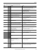
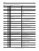
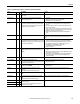
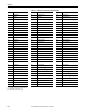
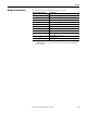
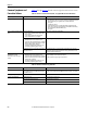
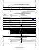
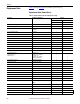
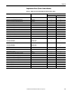
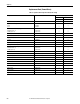
Table Of Contents
- Front Cover
- Important User Information
- Summary of Changes
- Table of Contents
- Introduction
- About the Drive
- Identifying the Drive by Cabinet Assembly ID Number
- LiquiFlo 2.0 Drive Component Locations
- Identifying the Power Module by Model Number
- AC Line I/O Board Description (Frame 3 Only)
- Standard I/O Board Description (Frame 3 Only)
- Combined I/O Board Description (Frame 4 Only)
- DPI Communication Ports
- Optional Equipment
- Planning the Installation
- Mounting The Power Module and Grounding the Drive
- Installing Input and Output Power Wiring
- Completing the Installation
- Using the Start-up Routines
- Programming Basics
- Parameter Descriptions
- Troubleshooting the Drive
- Verify that the DC Bus Capacitors are Discharged Before Servicing the Drive
- Determining Drive Status Using the Status LEDs
- About Alarms
- About Faults
- Diagnostic Parameters
- Common Symptoms and Corrective Actions
- Replacement Parts
- Board Replacement, Firmware Setup Procedures
- Troubleshooting the Drive Using the OIM
- Checking the Power Modules with Input Power Off
- Technical Specifications
- Using the OIM
- Installing and Removing the OIM
- Display Description
- OIM Menu Structure
- Powering Up and Adjusting the OIM
- Selecting a Device in the System
- Using the OIM to Program the Drive
- Monitoring the Drive Using the Process Display Screen on the OIM
- Displaying and Changing the OIM Reference
- Customizing the Process Display Screen
- Customizing the Function Keys
- Controlling the Drive From the OIM
- LiquiFlo 2.0 Drive Frame 3 Wiring Diagrams
- LiquiFlo 2.0 Drive Frame 4 Wiring Diagrams
- Index
- Back Cover
Rockwell Automation Publication D2-3518-3 - May 2013 217
Chapter 10
Table 26 - Drive Does Not Respond to Changes in Speed Command
Table 27 - Motor and/or Drive Does Not Accelerate to Commanded Speed
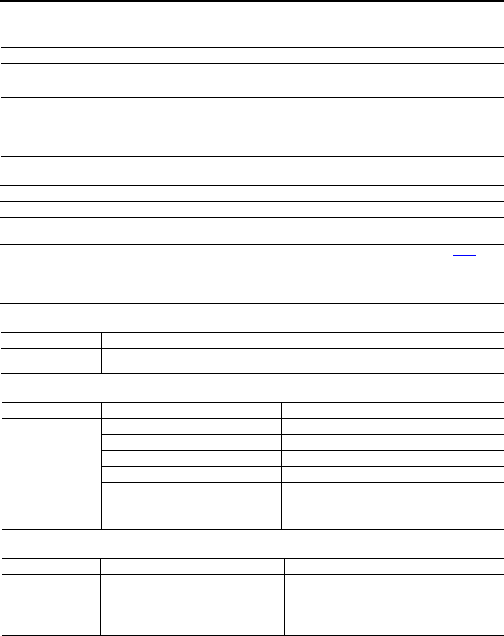
Table 28 - Motor Operation is Unstable
Table 29 - Drive Does Not Reverse Motor Direction
Table 30 - Stopping the Drive Results in a Decel Inhibit Fault
Indication Cause(s) Corrective Action
OIM Status Line indicates At
Speed and output is 0 Hz.
No value is coming from the source of the command. 1. If the source is an analog input, check wiring and use a meter to check for
presence of signal.
2. Check Commanded Freq (2) for correct source.
None Incorrect reference source has been programmed. 1. Check Speed Ref Source (213) for the source of the speed reference.
2. Reprogram Speed Ref A Sel (90) for correct source.
None Incorrect reference source is being selected via remote device or
digital inputs.
1. Check Drive Status 1 (209), bits 12...15 for unexpected source selections.
2. Check Dig In Status (216) to see if inputs are selecting an alternate source.
3. Reprogram digital inputs to correct Speed Sel x option.
Indication Cause(s) Corrective Action
Acceleration time is excessive. Incorrect value in Accel Time x (140, 141). Reprogram Accel Time x (140, 141).
Drive is forced into current limit,
slowing or stopping acceleration.
Excess load or short acceleration time. Check Drive Status 2 (210), bit 10 to see if the drive is in current limit.
Remove excess load or reprogram Accel Time x (140, 141).
Speed command source or value
is not as expected.
Improper speed command. Check for the proper speed command using steps 1...7 in table Tab le 26
.
Programming is preventing the
drive output from exceeding
limiting values.
Incorrect programming. Check Maximum Speed (82) and Maximum Freq (55) to insure that speed is not
limited by programming.
Indication Cause(s) Corrective Action
None Motor data was incorrectly entered or autotune was not
performed.
1. Correctly enter motor nameplate data.
2. Perform static or rotate autotune procedure (61).
Indication Cause(s) Corrective Action
None Digital input is not selected for reversing control. Check Digital Inx Sel. Choose correct input and program for reverse.
Digital input is incorrectly wired. Check input wiring.
Direction Mode (190) parameter is incorrectly programmed. Reprogram Direction Mode (190) for analog bipolar or digital unipolar control.
Motor wiring is improperly phased for reverse. Switch two motor leads.
A bipolar analog speed command input is incorrectly wired or
signal is absent.
1. Use meter to check that an analog input voltage is present.
2. Check wiring.
Positive voltage commands forward direction.
Negative voltage commands reverse direction.
Indication Cause(s) Corrective Action
Decel Inhibit fault screen.
LCD status line indicates Faulted.
The bus regulation feature is enabled and is halting deceleration
due to excessive bus voltage. Excess bus voltage is normally due
to excessive regenerated energy or unstable AC line input
voltages.
Internal timer has halted drive operation.
1. Reprogram bus regulation (parameters 161 and 162) to eliminate any
Adjust Freq selection.
2. Disable bus regulation (parameters 161 and 162) and add a dynamic
brake.
3. Correct AC input line instability or add an isolation transformer.
4. Reset drive.