
Owner's manual
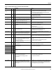
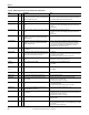
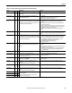
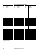
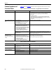
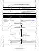
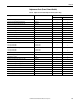
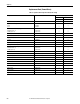
Table Of Contents
- Front Cover
- Important User Information
- Summary of Changes
- Table of Contents
- Introduction
- About the Drive
- Identifying the Drive by Cabinet Assembly ID Number
- LiquiFlo 2.0 Drive Component Locations
- Identifying the Power Module by Model Number
- AC Line I/O Board Description (Frame 3 Only)
- Standard I/O Board Description (Frame 3 Only)
- Combined I/O Board Description (Frame 4 Only)
- DPI Communication Ports
- Optional Equipment
- Planning the Installation
- Mounting The Power Module and Grounding the Drive
- Installing Input and Output Power Wiring
- Completing the Installation
- Using the Start-up Routines
- Programming Basics
- Parameter Descriptions
- Troubleshooting the Drive
- Verify that the DC Bus Capacitors are Discharged Before Servicing the Drive
- Determining Drive Status Using the Status LEDs
- About Alarms
- About Faults
- Diagnostic Parameters
- Common Symptoms and Corrective Actions
- Replacement Parts
- Board Replacement, Firmware Setup Procedures
- Troubleshooting the Drive Using the OIM
- Checking the Power Modules with Input Power Off
- Technical Specifications
- Using the OIM
- Installing and Removing the OIM
- Display Description
- OIM Menu Structure
- Powering Up and Adjusting the OIM
- Selecting a Device in the System
- Using the OIM to Program the Drive
- Monitoring the Drive Using the Process Display Screen on the OIM
- Displaying and Changing the OIM Reference
- Customizing the Process Display Screen
- Customizing the Function Keys
- Controlling the Drive From the OIM
- LiquiFlo 2.0 Drive Frame 3 Wiring Diagrams
- LiquiFlo 2.0 Drive Frame 4 Wiring Diagrams
- Index
- Back Cover

216 Rockwell Automation Publication D2-3518-3 - May 2013
Chapter 10
Common Symptoms and
Corrective Actions
Tab le 2 4 through Tab le 3 0 describe common symptoms and corrective actions.
Table 24 - Drive Does Not Start From Start, Run, or Jog Inputs Wired to the Terminal Block
Table 25 - Drive Does Not Start or Jog From OIM
Indication(s) Cause(s) Corrective Action
Flashing red Ready LED. Drive is faulted. Clear fault:
• Press OIM stop key. This action only succeeds if the clear faults function for that
OIM is enabled using the Logic Mask (276) and Fault Clr Mask (283).
• Cycle power.
• Set Fault Clear (240) to 1.
• Toggle terminal block stop or terminal block fault reset digital input. This
action only succeeds if the clear faults function for that OIM is enabled using
the Logic Mask (276) and Fault Clr Mask (283).
• Cycle power.
Incorrect operation from the terminal
block.
Incorrect input wiring.
• 2-wire control requires Run, Run Forward, or Run
Reverse input(s).
• 3-wire control requires Start and Stop inputs
• Jumper from terminal 7 to 8 is required.
Wire inputs correctly and/or install jumper.
Incorrect digital input programming.
• Mutually exclusive choices have been made.
• 2-wire and 3-wire programming may be conflicting.
• Exclusive functions (for example, direction control)
may have multiple inputs configured.
• Stop if factory default and is not wired or is open.
• Start or Run programming may be missing.
Program Digital Inx Sel (361...366) for correct inputs.
The Digital In bit of one or more of the mask parameters
(276...285) is not set.
Set the Digital In bit to 1 in the appropriate mask parameters (276...285). The
Digital In bit of the Logic Mask (276) must be set if any control function is to be
performed from the terminal block.
Flashing yellow Ready LED and DigIn
CflctB indication on OIM.
Drive Status 2 (210) shows type 2
alarm(s).
Incorrect digital input programming.
• Mutually exclusive choices have been made.
• 2-wire and 3-wire programming may be conflicting.
• Exclusive functions (i.e, direction control) may have
multiple inputs configured.
• Stop if factory default and is not wired or is open.
• Start or Run programming may be missing.
Program Digital Inx Sel (361...366) to resolve conflicts.
Remove multiple selections for the same function.
Install stop button to apply a signal at stop terminal.
Indication Cause(s) Corrective Action
None Drive is programmed for 2-wire control, and the bits of
the Logic Mask (276) and Start Mask (277) that apply
to the OIM are set to 1.
If 2-wire control is required, no action is necessary.
If 3-wire control is required, program Digital Inx Sel (361...366) for correct inputs.
Flashing or steady red Ready LED. Active fault. Reset fault.
Flashing yellow Ready LED. Enable input is open. Close terminal block enable input.
The terminal block stop input is open. Close terminal block stop input.
Start inhibit bits are set. Check status in Start Inhibits (214).