
Owner's manual
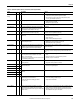
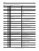
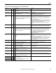
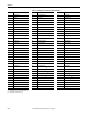
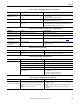
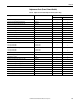
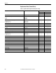
Table Of Contents
- Front Cover
- Important User Information
- Summary of Changes
- Table of Contents
- Introduction
- About the Drive
- Identifying the Drive by Cabinet Assembly ID Number
- LiquiFlo 2.0 Drive Component Locations
- Identifying the Power Module by Model Number
- AC Line I/O Board Description (Frame 3 Only)
- Standard I/O Board Description (Frame 3 Only)
- Combined I/O Board Description (Frame 4 Only)
- DPI Communication Ports
- Optional Equipment
- Planning the Installation
- Mounting The Power Module and Grounding the Drive
- Installing Input and Output Power Wiring
- Completing the Installation
- Using the Start-up Routines
- Programming Basics
- Parameter Descriptions
- Troubleshooting the Drive
- Verify that the DC Bus Capacitors are Discharged Before Servicing the Drive
- Determining Drive Status Using the Status LEDs
- About Alarms
- About Faults
- Diagnostic Parameters
- Common Symptoms and Corrective Actions
- Replacement Parts
- Board Replacement, Firmware Setup Procedures
- Troubleshooting the Drive Using the OIM
- Checking the Power Modules with Input Power Off
- Technical Specifications
- Using the OIM
- Installing and Removing the OIM
- Display Description
- OIM Menu Structure
- Powering Up and Adjusting the OIM
- Selecting a Device in the System
- Using the OIM to Program the Drive
- Monitoring the Drive Using the Process Display Screen on the OIM
- Displaying and Changing the OIM Reference
- Customizing the Process Display Screen
- Customizing the Function Keys
- Controlling the Drive From the OIM
- LiquiFlo 2.0 Drive Frame 3 Wiring Diagrams
- LiquiFlo 2.0 Drive Frame 4 Wiring Diagrams
- Index
- Back Cover

214 Rockwell Automation Publication D2-3518-3 - May 2013
Chapter 10
Table 23 - Fault Names Cross-Referenced by Fault Number
No.
(1)
Fault No.
(1)
Fault No.
(1)
Fault
2 Auxiliary Input 48 Params Defaulted 214 Reactor Temp
3 Power Loss 63 Shear Pin 215 Rctfr HW Unused
(3)
4 UnderVoltage 64 Drive Overload 216 Rctfr Gnd Fault
5 OverVoltage 70 HW Fault 217 Rctfr Base Temp
7 Motor Overload 71...76 Port 1...6 Adapter 218 Rctfr IGBT Temp
8 Invtr Base Temp 77 IR Volts Range 219 Rctfr IT Overld
9 Invtr IGBT Temp 78 FluxAmpsRef Rang 220 Rctfr I2T Overld
12 HW OverCurrent 79 Excessive Load 221 Ride Thru Abort
13 Ground Fault 80 AutoTune Aborted 222 High AC Line
14 Inv Shunt Trip 81...86 Port 1...6 DPI Loss 223 Low DC Bus
15 Hi Vdc Shunt 87 IXo VoltageRange 224 Rctfr Over Volt
18 Invtr I Offset U 100 Parameter Chksum 225 Input I Imbalance
19 Invtr I Offset V 101 UserSet1 Chksum 226 Input V Imbalance
20 Invtr I Offset W 102 UserSet2 Chksum 227 AC Line Lost
21 Rctfr I Offset R 103 UserSet3 Chksum 228 Line Feq Lost
22 Rctfr I Offset S 104 Pwr Brd Chksum1 229 Rctfr Checksum
23 Rctfr I Offset T 105 Pwr Brd Chksum2 230 Invtr HW Unk
24 Decel Inhibit 106 Incompat MCB-PB 231 Rctfr HW Unk
25 OverSpeed Limit 107 Replaced MCB-PB 232 Rctfr Not OK
29 Analog In Loss 120 I/O Mismatch
(3)
233 Precharge Closed
30 NTC Demux Fail
(2)
121 I/O Comm Loss 234 Precharge Opened
31 Inv Temp Switch
(2)
122 I/O Board Fail 3 235 Rctfr Pwr Board
33 Auto Rstrt Tries 123 Invtr Unk IO Brd
(2)
236 Rctfr IO Board
35 Current Fbk Lost 197...199 Invtr Dsat U-, V-, W-
(2)
237 Not At Voltage
36 SW OverCurrent 200...202 Invtr Dsat U, V, W
(3)
238 Rctfr Not Login
37 Motor I Imbalance 200...202 Invtr Dsat U+, V+, W+
(2)
239 Power Phased ACB
38 Phase U to Grnd 203...205 Invtr Over Cur U, V, W 240 Rctfr Gate Kill
(2)
39 Phase V to Grnd 206 Invtr HW Unused
(3)
241...243 Rctfr Dsat R-, S-, T-
(2)
40 Phase W to Grnd 207 Invtr Gate Kill 244 Rctfr NTC Demux
(2)
41 Phase UV Short 208...210 Rctfr Dsat R, S, T
(3)
245 Rctfr Unk IO Brd
(2)
42 Phase VW Short 208...210 Rctfr Dsat R+, S+, T +
(2)
246 Rctfr DPI Comm
(2)
43 Phase WU Short 211...213 Rctfr Over Cur R, S, T 247 CarrierSync Lost
(1) Fault numbers not listed are reserved for future use.
(2) Fault available on Frame 4 drives only.
(3) Fault available on Frame 3 drives only.