
Owner's manual
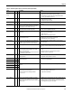
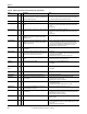
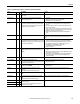
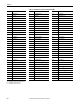
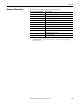
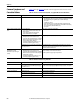
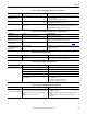
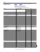
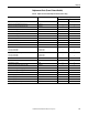
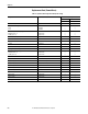
Table Of Contents
- Front Cover
- Important User Information
- Summary of Changes
- Table of Contents
- Introduction
- About the Drive
- Identifying the Drive by Cabinet Assembly ID Number
- LiquiFlo 2.0 Drive Component Locations
- Identifying the Power Module by Model Number
- AC Line I/O Board Description (Frame 3 Only)
- Standard I/O Board Description (Frame 3 Only)
- Combined I/O Board Description (Frame 4 Only)
- DPI Communication Ports
- Optional Equipment
- Planning the Installation
- Mounting The Power Module and Grounding the Drive
- Installing Input and Output Power Wiring
- Completing the Installation
- Using the Start-up Routines
- Programming Basics
- Parameter Descriptions
- Troubleshooting the Drive
- Verify that the DC Bus Capacitors are Discharged Before Servicing the Drive
- Determining Drive Status Using the Status LEDs
- About Alarms
- About Faults
- Diagnostic Parameters
- Common Symptoms and Corrective Actions
- Replacement Parts
- Board Replacement, Firmware Setup Procedures
- Troubleshooting the Drive Using the OIM
- Checking the Power Modules with Input Power Off
- Technical Specifications
- Using the OIM
- Installing and Removing the OIM
- Display Description
- OIM Menu Structure
- Powering Up and Adjusting the OIM
- Selecting a Device in the System
- Using the OIM to Program the Drive
- Monitoring the Drive Using the Process Display Screen on the OIM
- Displaying and Changing the OIM Reference
- Customizing the Process Display Screen
- Customizing the Function Keys
- Controlling the Drive From the OIM
- LiquiFlo 2.0 Drive Frame 3 Wiring Diagrams
- LiquiFlo 2.0 Drive Frame 4 Wiring Diagrams
- Index
- Back Cover

Rockwell Automation Publication D2-3518-3 - May 2013 213
Chapter 10
Rctfr Not OK 232 4 A fault was detected on the rectifier but could not be displayed
on the inverter.
Look at rectifier parameter 243 to see fault code.
Rctfr NTC Demux 244 4 Control board cannot read temperature information from
rectifier half of power board.
1. Clear faults.
2. If fault persists, verify connections to power board.
3. If fault still persists, replace power board.
Rctfr Over Cur
R, S, T
211
212
213
4 Rectifier overcurrent.
See description of rectifier IOC Redir Time (300) and IOC Redir
Max (301) for discussion of alternative reporting of rectifier
instantaneous overcurrent (IOC) faults.
1. High line current can be caused by high load current. Verify that rectifier
overcurrent was not caused by sudden increase in motor (inverter)
current.
2. Low input voltage can result in increased current load. Provide proper
input voltage to the drive.
3. AC line events such as short duration shorts in the nearby grid can cause
sudden line current increases. Verify that such events have not occurred.
4. Verify proper motor data is entered on inverter.
5. Reduce rectifier current limit using rectifier Current Limit parameter
(105).
Rctfr Over Volt 224 4 The DC bus voltage is too high. Monitor the AC line for high line voltage or transient conditions. Bus
overvoltage can also be caused by motor regeneration. Extend the decel
time.
Rctfr Pwr Board 235 2 Drive rating information stored on the power board is
incompatible with rectifier application firmware, or drive rating
information stored on the power board was corrupted or could
not be read by rectifier firmware.
1. Check connections between Combined Control board and Combined
Power board. If this fixes the problem, use inverter Reset To Defaults
(inverter 197) and rectifier Reset To Defaults (rectifier 197) to reset all
drive parameters to defaults, then reconfigure drive as necessary.
2. Load updated drive rating information onto rectifier.
3. Load updated rectifier application firmware.
4. Replace power board.
Rctfr Unk IO Brd 245 4 The I/O board is of a type that is unknown to the rectifier
firmware. If fault is cleared, analog inputs and outputs are
unusable.
1. Verify that I/O Board ID Voltage (rectifier 354) is correct for this type of I/O
board.
2. If ID voltage is not correct, then replace I/O board. If ID voltage is still not
correct, then replace control board.
3. If ID voltage is correct, verify that current rectifier application firmware
version can use this type of I/O board. If not, then update rectifier
application firmware.
Reactor Temp 214 4 Temperature switch in reactor opened. Check for proper temperature and fan operation.
Replaced MCB-PB 107 2 Control board or power board was replaced.
This fault can be cleared by writing a nonzero value to inverter
Reset To Defaults parameter (197).
1. Restore inverter defaults (inverter parameter 197).
2. Reprogram parameters.
Ride Thru Abort 221 4 Input power loss timed out, rectifier Ride Through Ena
(rectifier 64) is set to Enabled.
1. Verify input power and connections.
2. Check I/O board.
Shear Pin 63 1
3
Programmed inverter Current Lmt Val (148) has been
exceeded.
Enabled/disable with inverter Fault Config 1 (238).
Check load requirements and inverter Current Lmt Val (148) setting.
SW OverCurrent 36 1 The drive output current has exceeded the software current
limit.
Check for excess load, improper DC boost setting. DC brake volts set too high.
UnderVoltage 4
1
3
DC bus voltage fell below the minimum value of: 305V DC
input.
Enable/disable with inverter Fault Config 1(238).
Monitor the incoming AC line for low voltage or power interruption.
UserSet1 Chksum 101 2 The checksum read from the user set does not match the
checksum calculated.
These faults can be cleared by writing a nonzero value to
inverter Save To User Set (199).
Re-save user set using inverter Save To User Set (199).
UserSet2 Chksum 102 2
UserSet3 Chksum 103 2
Table 22 - Fault Descriptions and Corrective Actions (Frame 4) (Continued)
Fault
No.
Type
Description Action