
Owner's manual
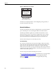
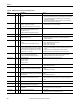
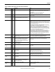
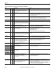
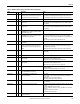
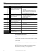
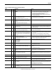
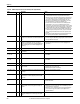
Table Of Contents
- Front Cover
- Important User Information
- Summary of Changes
- Table of Contents
- Introduction
- About the Drive
- Identifying the Drive by Cabinet Assembly ID Number
- LiquiFlo 2.0 Drive Component Locations
- Identifying the Power Module by Model Number
- AC Line I/O Board Description (Frame 3 Only)
- Standard I/O Board Description (Frame 3 Only)
- Combined I/O Board Description (Frame 4 Only)
- DPI Communication Ports
- Optional Equipment
- Planning the Installation
- Mounting The Power Module and Grounding the Drive
- Installing Input and Output Power Wiring
- Completing the Installation
- Using the Start-up Routines
- Programming Basics
- Parameter Descriptions
- Troubleshooting the Drive
- Verify that the DC Bus Capacitors are Discharged Before Servicing the Drive
- Determining Drive Status Using the Status LEDs
- About Alarms
- About Faults
- Diagnostic Parameters
- Common Symptoms and Corrective Actions
- Replacement Parts
- Board Replacement, Firmware Setup Procedures
- Troubleshooting the Drive Using the OIM
- Checking the Power Modules with Input Power Off
- Technical Specifications
- Using the OIM
- Installing and Removing the OIM
- Display Description
- OIM Menu Structure
- Powering Up and Adjusting the OIM
- Selecting a Device in the System
- Using the OIM to Program the Drive
- Monitoring the Drive Using the Process Display Screen on the OIM
- Displaying and Changing the OIM Reference
- Customizing the Process Display Screen
- Customizing the Function Keys
- Controlling the Drive From the OIM
- LiquiFlo 2.0 Drive Frame 3 Wiring Diagrams
- LiquiFlo 2.0 Drive Frame 4 Wiring Diagrams
- Index
- Back Cover

Rockwell Automation Publication D2-3518-3 - May 2013 209
Chapter 10
Table 22 - Fault Descriptions and Corrective Actions (Frame 4)
Fault
No.
Typ e
Description Action
AC Line Lost 227 4 Input power Lost, rectifier Ride Through Ena (64) is set to
Disabled.
1. Verify proper input voltage.
2. Use rectifier parameters Line Frequency (1), Input Voltage RS (7),
Input Voltage ST (8), Input Voltage TR (9) to verify that drive can
accurately measure input frequency and voltage.
3. Check line voltage feedback signal path, including Combined I/O board
and Combined Control board.
Analog In Loss 29 1 A user-configurable analog input is configured to fault on
signal loss. A signal loss has occurred.
Configure with inverter Analog In 1, 2 Loss (324, 327).
1. Check parameters.
2. Check for broken/loose connections at inputs.
Auto Rstrt Tries 33 3 Drive unsuccessfully attempted to reset a fault and resume
running for the programmed number of inverter Auto Rstrt
Tries (174).
Enable/disable with inverter Fault Config 1 (238).
Correct the cause of the fault and manually clear.
AutoTune Aborted 80 4 You canceled the autotune procedure. Restart procedure.
Auxiliary Input 2 1 A user-configurable digital input is configured to Aux. Fault
and the input is open.
1. Check digital input wiring.
2. Configure the digital input to something else with inverter Digital In Sel
parameter (361...366).
CarrierSync Lost 247 3 Rectifier could not maintain carrier synchronization to inverter.
Configure with rectifier Fault Config (rectifier 238).
1. Set inverter PWM Frequency (inverter 151) to 4 KHz.
2. Replace combined control board.
Current Fbk Lost 35 4 The magnitude of motor current feedback was less than 5% of
inverter Motor NP FLA (42) for the time configured in inverter
Imbalance Time (50). Detection of this fault is disabled when
inverter Imbalance Time (50) is set to the maximum value of
10.0 seconds.
1. If motor current rating is significantly less than drive output rating, it may
be necessary to disable this fault by setting inverter Imbalance Time (50)
to 10.0 seconds.
2. Verify connection of current feedback device and motor terminals.
3. If fault repeats, replace current feedback devices and/or power supply.
Decel Inhibit 24 3 The drive is not following a commanded deceleration because
it is attempting to limit bus voltage.
Enable/disable with inverter Fault Config 1 (238).
1. Verify input voltage is within drive specified limits.
2. Verify system ground impedance follows proper grounding techniques.
3. Disable bus regulation and/or extend deceleration time.
Drive OverLoad 64 1 Drive output rating of
110% for 1 minute or
150% for 5 seconds
has been exceeded.
Reduce load or extend inverter Accel Time (140, 141).
Excessive Load 79 4 Motor did not come up to speed in the allotted time. 1. Uncouple load from motor.
2. Repeat Autotune (inverter 61).
FluxAmpsRef Rang 78 4 The value for flux amps determined by the autotune procedure
exceeds the programmed inverter Motor NP FLA (42).
1. Reprogram inverter Motor NP FLA (42) with the correct motor nameplate
value.
2. Repeat Autotune (inverter 61).
Ground Fault 13 1 A current path to earth ground in excess of 50% of drive rated
amps has been detected at one or more of the drive output
terminals.
Check the motor and external wiring to the drive output terminals for a
grounded condition. See inverter Ground Current (21).
Hi Vdc Shunt 15 4 Drive has activated the shunt trip because the DC Bus Voltage
was above 800V DC for more than 100ms.
1. Monitor the AC line for high line voltage or transient conditions.
2. Bus overvoltage can also be caused by motor regeneration. Extend the
decel time.
High AC Line 222 4 Input line voltage is too high. Reduce input voltage to meet specification of 480 ±10%.
HW Fault 70 4 Inverter section of power structure hardware detected an
unexpected fault during power stage diagnostics.
Replace power board.
HW OverCurrent 12 1 The drive output current has exceeded the hardware current
limit.
Check programming. Check for excess load, improper DC boost setting, DC
brake volts set too high or other causes of excess current.
I/O Comm Loss 121 4 Communication between control board and I/O board has not
been established.
1. Clear fault.
2. If fault persists, verify connection between I/O board and control board.
3. If fault still persists, replace I/O board.
4. If fault still persists, replace control board.
Incompat MCB-PB 106 2 Drive rating information stored on the combined power board
inverter EEPROM is incompatible with the Combined Control
board inverter firmware.
Load compatible version files into inverter.