
Owner's manual
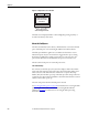
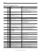
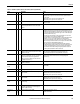
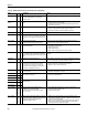
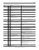
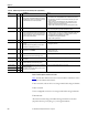
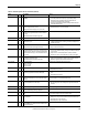
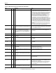
Table Of Contents
- Front Cover
- Important User Information
- Summary of Changes
- Table of Contents
- Introduction
- About the Drive
- Identifying the Drive by Cabinet Assembly ID Number
- LiquiFlo 2.0 Drive Component Locations
- Identifying the Power Module by Model Number
- AC Line I/O Board Description (Frame 3 Only)
- Standard I/O Board Description (Frame 3 Only)
- Combined I/O Board Description (Frame 4 Only)
- DPI Communication Ports
- Optional Equipment
- Planning the Installation
- Mounting The Power Module and Grounding the Drive
- Installing Input and Output Power Wiring
- Completing the Installation
- Using the Start-up Routines
- Programming Basics
- Parameter Descriptions
- Troubleshooting the Drive
- Verify that the DC Bus Capacitors are Discharged Before Servicing the Drive
- Determining Drive Status Using the Status LEDs
- About Alarms
- About Faults
- Diagnostic Parameters
- Common Symptoms and Corrective Actions
- Replacement Parts
- Board Replacement, Firmware Setup Procedures
- Troubleshooting the Drive Using the OIM
- Checking the Power Modules with Input Power Off
- Technical Specifications
- Using the OIM
- Installing and Removing the OIM
- Display Description
- OIM Menu Structure
- Powering Up and Adjusting the OIM
- Selecting a Device in the System
- Using the OIM to Program the Drive
- Monitoring the Drive Using the Process Display Screen on the OIM
- Displaying and Changing the OIM Reference
- Customizing the Process Display Screen
- Customizing the Function Keys
- Controlling the Drive From the OIM
- LiquiFlo 2.0 Drive Frame 3 Wiring Diagrams
- LiquiFlo 2.0 Drive Frame 4 Wiring Diagrams
- Index
- Back Cover

Rockwell Automation Publication D2-3518-3 - May 2013 207
Chapter 10
Power Loss 3 1
3
Input power unavailable or AC line synchronization not
possible for longer than inverter Power Loss Time (185).
Enable/disable with inverter Fault Config 1 (238).
1. Monitor the incoming AC line for low voltage or line power interruption.
2. Check AC line voltage feedback wiring and signal path. This includes the line
synchronization board, the AC Line I/O board, and the rectifier control board.
Power Phased ACB 239 4 Input power is phased ACB rather than ABC. Switch two of the input power phases.
Precharge Closed 233 4 One or more precharge contactors was closed when it
should be open.
1. Check AUX contacts on precharge contactor(s).
2. Check bit 0 in rectifier parameter Dig In Status (216) to view status of input.
3. Check wiring.
Precharge Open 234 4 One or more precharge contactors was open when it
should be closed.
1. Check AUX contacts on precharge contactor(s).
2. Check bit 0 in rectifier parameter Dig In Status (216) to view status of input.
3. Check wiring.
Pwr Brd Chksum1 104 4 The checksum read from the inverter power interface
board EEPROM does not match the checksum calculated
from the EEPROM status data.
Clear the fault or cycle power to the drive.
Pwr Brd Chksum2 105 2 The checksum read from the inverter power interface
board EEPROM does not match the checksum calculated
from the EEPROM configuration data.
1. Check connections between inverter control board and inverter power
interface board. If this fixes the issue, then use inverter Reset To Defaults
(inverter 197) to reset the rectifier to its defaults, then reconfigure the drive as
needed.
2. If problem persists, replace inverter power interface board.
Rctfr Base Temp 217 4 Measured temperature of one of the rectifier IGBT modules
exceeded limits.
Check for proper temperature and flow rate of coolant.
Rctfr Checksum 229 4 The parameter checksum read from the rectifier control
board does not match the checksum calculated, or the
rectifier power board or rectifier control board has been
replaced.
1. Clear fault.
2. If fault persists, restore defaults on rectifier (rectifier parameter 197), then
reprogram rectifier parameters.
3. If fault still persists, replace rectifier control board or rectifier power board.
Rctfr Dsat R, S, T 208
209
210
4 High current was detected in an IGBT. 1. Check for loose connection in IGBT wire harness.
2. Check IGBTs.
Rctfr Gnd Fault 216 4 Excessive input ground current measured. Check for grounded input wiring.
Rctfr HW Unk 231 4 Rectifier portion of power structure hardware reported
unexpected fault.
1. Verify connection between rectifier control board and rectifier power board.
2. If fault persists, replace rectifier power board.
3. If fault still persists, replace rectifier inverter control board.
Rctfr HW Unused 215 4 Rectifier portion of power structure hardware reported
unexpected fault.
1. Verify connection between rectifier control board and rectifier power board.
2. If fault persists, replace rectifier power board.
3. If fault still persists, replace rectifier inverter control board.
Rctfr I2T Ovrld 220 4 Long-term current rating of rectifier exceeded. 1. Low input voltage can result in increased current load. Provide proper input
voltage to the drive.
2. Verify that rectifier Input Load Amps (106) is set correctly.
Rctfr IGBT Temp 218 4 Excessive calculated rectifier IGBT junction temperature.
See rectifier Rctfr IGBT Temp (rectifier 19).
Check for proper temperature and flow rate of coolant.
Rctfr IO Board 236 2 Loss of communication to rectifier I/O board.
Rectifier I/O board failure.
1. Clear fault.
2. If fault persists, verify connection between rectifier I/O board and rectifier
control board.
3. If fault still persists, replace rectifier I/O board.
4. If fault still persists, replace rectifier control board.
Rctfr IT Overld 219 4 Short-term current rating of rectifier exceeded. Low input voltage can result in increased current load. Provide proper input
voltage to the drive.
Rctfr Not Login 238 4 Rectifier took too long to connect to inverter. 1. Check the cabling between the communications interface and the two control
boards.
2. Verify the DPI Data Rate (270) is set to 500K.
3. Connect one DPI device at a time to see if one of the DPI devices is causing the
problem.
4. Replace the communications interface.
5. Replace the rectifier control board.
Rctfr Not OK 232 4 A fault was detected on the rectifier but could not be
displayed on the inverter.
Look at rectifier parameter 243 to see fault code.
Table 21 - Fault Descriptions and Corrective Actions (Frame 3) (Continued)
Fault
No.
Type
Description Action