
Owner's manual
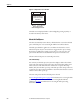
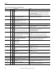
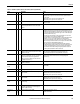
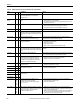
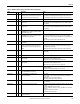
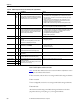
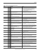
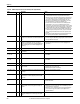
Table Of Contents
- Front Cover
- Important User Information
- Summary of Changes
- Table of Contents
- Introduction
- About the Drive
- Identifying the Drive by Cabinet Assembly ID Number
- LiquiFlo 2.0 Drive Component Locations
- Identifying the Power Module by Model Number
- AC Line I/O Board Description (Frame 3 Only)
- Standard I/O Board Description (Frame 3 Only)
- Combined I/O Board Description (Frame 4 Only)
- DPI Communication Ports
- Optional Equipment
- Planning the Installation
- Mounting The Power Module and Grounding the Drive
- Installing Input and Output Power Wiring
- Completing the Installation
- Using the Start-up Routines
- Programming Basics
- Parameter Descriptions
- Troubleshooting the Drive
- Verify that the DC Bus Capacitors are Discharged Before Servicing the Drive
- Determining Drive Status Using the Status LEDs
- About Alarms
- About Faults
- Diagnostic Parameters
- Common Symptoms and Corrective Actions
- Replacement Parts
- Board Replacement, Firmware Setup Procedures
- Troubleshooting the Drive Using the OIM
- Checking the Power Modules with Input Power Off
- Technical Specifications
- Using the OIM
- Installing and Removing the OIM
- Display Description
- OIM Menu Structure
- Powering Up and Adjusting the OIM
- Selecting a Device in the System
- Using the OIM to Program the Drive
- Monitoring the Drive Using the Process Display Screen on the OIM
- Displaying and Changing the OIM Reference
- Customizing the Process Display Screen
- Customizing the Function Keys
- Controlling the Drive From the OIM
- LiquiFlo 2.0 Drive Frame 3 Wiring Diagrams
- LiquiFlo 2.0 Drive Frame 4 Wiring Diagrams
- Index
- Back Cover

Rockwell Automation Publication D2-3518-3 - May 2013 205
Chapter 10
I/O Comm Loss 121 2 Loss of communication to inverter standard I/O board. 1. Cycle power.
2. If fault persists, verify connection between inverter I/O board and inverter
control board.
3. If fault still persists, replace inverter standard I/O board.
4. If fault still persists, replace inverter control board.
I/O Mismatch 120 4 Incorrect inverter I/O board identified. Restore inverter I/O board to original configuration, or If new configuration is
desired, reset fault.
Incompat MCB-PB 106 2 Drive rating information stored on the inverter power
board is incompatible with the inverter Control board
firmware.
Load compatible version files into inverter.
Input I Imbalance 225 4 Input phase current imbalance exceeded limits. 1. Fault 225 can occur if rectifier Line I Imbalance (22) is greater than rectifier I
Imbalance Lmt (62) for longer than the time in rectifier I Imbalance Time (63).
Verify that rectifier parameters 62 and 63 have the correct values. If this is the
cause of the fault 225, fault 225 should also appear in the rectifier fault queue
(rectifier parameters 243...250).
2. Check for line voltage imbalance. A line voltage imbalance can cause a line
current imbalance. See rectifier Line V Imbalance (23).
3. Check for existence of rectifier instantaneous overcurrent (IOC) faults (rectifier
faults 12, 211, 212, 213) in rectifier fault queue (rectifier parameters
243...250). Short duration events on AC line can cause rectifier overcurrents,
which can be reported as drive fault 225. See description of rectifier IOC Redir
Time (rectifier 300) and IOC Redir Max (rectifier 301).
4. Check for existence of rectifier Line V Imbal OL fault (rectifier fault 16) in
rectifier fault queue (rectifier parameters 243...250). This rectifier fault can be
caused by short duration AC line events and is reported as drive fault 225.
5. Check rectifier current feedback wiring and signal path, which includes the
rectifier power board and the rectifier control board.
Input V Imbalance 226 4 Rectifier Line V Imbalance (23) exceeded rectifier
V Imbalance Lmt (60) for more than the time in rectifier
V Imbalance Time (61).
1. Check for problem in input power distribution.
2. Check line voltage feedback wiring and signal path: includes line
synchronization board, AC Line I/O board, Rectifier control board.
Inv Shunt Trip 14 4 Drive has activated the shunt trip because the inverter
firmware has commanded it. This can be caused by the
detection of a motor-side (inverter) ground fault
(fault 13), or by the user writing a 1 to bit 0 of inverter
Appl Digital Out (inverter 30).
1. See table entry for Ground Fault (13).
2. Determine why a 1 was written to bit 0 of inverter Appl Digital Out
(inverter 30).
Invtr Base Temp 8 1 Measured temperature of one of the inverter IGBT
modules exceeded limit.
Check for proper temperature and flow rate of coolant.
Invtr Dsat
U, V, W
200
201
202
4 High current was detected in an IGBT. 1. Check for loose connection in IGBT wire harness.
2. Check IGBTs.
Invtr Gate Kill 207 4 Inverter gate kill contact is open. Close gate kill contact.
Invtr HW Unk 230 4 Inverter section of power structure hardware reported
unexpected fault.
1. Verify connection between inverter control board and inverter power board.
2. If fault persists, replace inverter power board.
3. If fault still persists, replace inverter control board.
Invtr HW Unused 206 4 Inverter section of power structure hardware reported
unexpected fault.
1. Verify connection between inverter control board and inverter power board.
2. If fault persists, replace inverter power board.
3. If fault still persists, replace inverter control board.
Invtr I Offset
U, V, W
18
19
20
4 An inverter current feedback offset calculated at drive start
was out of range.
Check inverter current feedback signal path.
Invtr IGBT Temp 9 1 Calculated inverter IGBT junction temperature has
exceeded its rated maximum. See inverter diagnostic
parameter 2, IGBT Junct Temp.
Check for proper temperature and flow rate of coolant.
Invtr Over Cur
U, V, W
203
204
205
4 High current was detected in an IGBT. 1. Verify proper motor data is entered.
2. Reduce current limit.
Table 21 - Fault Descriptions and Corrective Actions (Frame 3) (Continued)
Fault
No.
Type
Description Action