
Owner's manual
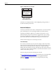
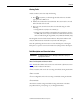
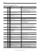
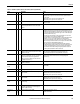
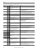
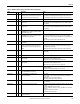
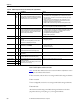
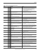
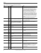
Table Of Contents
- Front Cover
- Important User Information
- Summary of Changes
- Table of Contents
- Introduction
- About the Drive
- Identifying the Drive by Cabinet Assembly ID Number
- LiquiFlo 2.0 Drive Component Locations
- Identifying the Power Module by Model Number
- AC Line I/O Board Description (Frame 3 Only)
- Standard I/O Board Description (Frame 3 Only)
- Combined I/O Board Description (Frame 4 Only)
- DPI Communication Ports
- Optional Equipment
- Planning the Installation
- Mounting The Power Module and Grounding the Drive
- Installing Input and Output Power Wiring
- Completing the Installation
- Using the Start-up Routines
- Programming Basics
- Parameter Descriptions
- Troubleshooting the Drive
- Verify that the DC Bus Capacitors are Discharged Before Servicing the Drive
- Determining Drive Status Using the Status LEDs
- About Alarms
- About Faults
- Diagnostic Parameters
- Common Symptoms and Corrective Actions
- Replacement Parts
- Board Replacement, Firmware Setup Procedures
- Troubleshooting the Drive Using the OIM
- Checking the Power Modules with Input Power Off
- Technical Specifications
- Using the OIM
- Installing and Removing the OIM
- Display Description
- OIM Menu Structure
- Powering Up and Adjusting the OIM
- Selecting a Device in the System
- Using the OIM to Program the Drive
- Monitoring the Drive Using the Process Display Screen on the OIM
- Displaying and Changing the OIM Reference
- Customizing the Process Display Screen
- Customizing the Function Keys
- Controlling the Drive From the OIM
- LiquiFlo 2.0 Drive Frame 3 Wiring Diagrams
- LiquiFlo 2.0 Drive Frame 4 Wiring Diagrams
- Index
- Back Cover

Rockwell Automation Publication D2-3518-3 - May 2013 203
Chapter 10
Clearing Faults
A fault condition can be cleared by the following:
1. Press or any F-Key to acknowledge the fault and remove the fault
pop-up from the OIM screen.
2. Address the condition that caused the fault. The cause must be corrected
before the fault can be cleared.
3. After corrective action has been taken, clear the fault using one of the
following:
• Setting Fault Clear (240) to Clear Faults (1).
• Issuing a Stop-Clear Faults command from the control device (such as
an OIM). This action only succeeds if the clear faults function for that
device is enabled using the Logic Mask (276) and Fault Clr Mask (283).
Resetting faults clears the faulted status indication. If any fault condition still
exists, the fault is latched, and another entry made in the fault queue.
Note that performing a fault reset does not clear the fault queue. Clearing the
fault queue is a separate action. See the Fault Clear (240) parameter description.
Fault Descriptions and Corrective Actions
Frame 3 Fault Descriptions and Corrective Actions
Tab le describes drive faults and corrective actions for Frame 3 (firmware version
1.x only). It also indicates if the fault is:
1 Auto-resettable, and can also be reset using normal fault clearing mechanisms
2 Non-resettable
3 User-configurable, and can be reset using normal fault clearing mechanisms
4 Normal fault*
*The fault is resettable using normal fault clearing mechanisms on the drive
(Stop/Reset button, powercycling, etc.) or through VS Utilities.
IMPORTANT
Read all faults from the inverter. Although rectifier faults occur, they are
displayed on the inverter.
ESC/
PROG