
Owner's manual
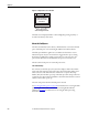
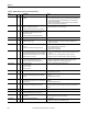
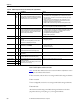
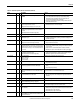
Table Of Contents
- Front Cover
- Important User Information
- Summary of Changes
- Table of Contents
- Introduction
- About the Drive
- Identifying the Drive by Cabinet Assembly ID Number
- LiquiFlo 2.0 Drive Component Locations
- Identifying the Power Module by Model Number
- AC Line I/O Board Description (Frame 3 Only)
- Standard I/O Board Description (Frame 3 Only)
- Combined I/O Board Description (Frame 4 Only)
- DPI Communication Ports
- Optional Equipment
- Planning the Installation
- Mounting The Power Module and Grounding the Drive
- Installing Input and Output Power Wiring
- Completing the Installation
- Using the Start-up Routines
- Programming Basics
- Parameter Descriptions
- Troubleshooting the Drive
- Verify that the DC Bus Capacitors are Discharged Before Servicing the Drive
- Determining Drive Status Using the Status LEDs
- About Alarms
- About Faults
- Diagnostic Parameters
- Common Symptoms and Corrective Actions
- Replacement Parts
- Board Replacement, Firmware Setup Procedures
- Troubleshooting the Drive Using the OIM
- Checking the Power Modules with Input Power Off
- Technical Specifications
- Using the OIM
- Installing and Removing the OIM
- Display Description
- OIM Menu Structure
- Powering Up and Adjusting the OIM
- Selecting a Device in the System
- Using the OIM to Program the Drive
- Monitoring the Drive Using the Process Display Screen on the OIM
- Displaying and Changing the OIM Reference
- Customizing the Process Display Screen
- Customizing the Function Keys
- Controlling the Drive From the OIM
- LiquiFlo 2.0 Drive Frame 3 Wiring Diagrams
- LiquiFlo 2.0 Drive Frame 4 Wiring Diagrams
- Index
- Back Cover
202 Rockwell Automation Publication D2-3518-3 - May 2013
Chapter 10
Figure 81 - Sample Fault Screen on the OIM
The fault screen is displayed until it is acknowledged by pressing any F-key or
cleared in the drive by other means.
About the Fault Queue
The drive automatically retains a history of faults that have occurred in the fault
queue. The fault queue is accessed using the OIM or VS Utilities software.
The fault queue holds the eight most recent faults. The last fault to occur is
indicated in queue entry #1. As new faults are logged into the queue, existing
fault entries are shifted (for example, entry #1 moves to entry #2). Once the
queue is full, older faults are discarded from the queue as new faults occur.
All entries in the fault queue are retained if power is lost.
The Time Stamp
For each entry in the fault queue, the system also displays a fault code and time
stamp value. The time stamp value is the value of an internal drive-under-power
timer at the time of the fault. The value of this timer is copied to PowerUp
Marker (242) when the drive powers up. The fault queue time stamp can then be
compared to the value in PowerUp Marker to determine when the fault occurred
relative to the last drive power up.
The time stamp is cleared when the fault queue is cleared.
See Accessing the Fault Queue
on page 226 for information on accessing the fault
queue using the OIM. Refer to the VS Utilities Getting Results Manual,
publication D2-3488
, for information on accessing the fault queue using
VS Utilities software.
Press any F Key to
Acknowledge the Fault
Fault Auto
ACKNOWLEDGE
- Fault - Fxxxxx
Fault Text String
Time Since Fault
xxxx:xx:xx