
Owner's manual
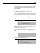
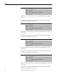
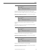
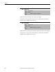
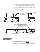
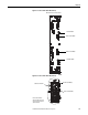
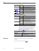
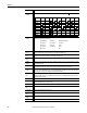
Table Of Contents
- Front Cover
- Important User Information
- Summary of Changes
- Table of Contents
- Introduction
- About the Drive
- Identifying the Drive by Cabinet Assembly ID Number
- LiquiFlo 2.0 Drive Component Locations
- Identifying the Power Module by Model Number
- AC Line I/O Board Description (Frame 3 Only)
- Standard I/O Board Description (Frame 3 Only)
- Combined I/O Board Description (Frame 4 Only)
- DPI Communication Ports
- Optional Equipment
- Planning the Installation
- Mounting The Power Module and Grounding the Drive
- Installing Input and Output Power Wiring
- Completing the Installation
- Using the Start-up Routines
- Programming Basics
- Parameter Descriptions
- Troubleshooting the Drive
- Verify that the DC Bus Capacitors are Discharged Before Servicing the Drive
- Determining Drive Status Using the Status LEDs
- About Alarms
- About Faults
- Diagnostic Parameters
- Common Symptoms and Corrective Actions
- Replacement Parts
- Board Replacement, Firmware Setup Procedures
- Troubleshooting the Drive Using the OIM
- Checking the Power Modules with Input Power Off
- Technical Specifications
- Using the OIM
- Installing and Removing the OIM
- Display Description
- OIM Menu Structure
- Powering Up and Adjusting the OIM
- Selecting a Device in the System
- Using the OIM to Program the Drive
- Monitoring the Drive Using the Process Display Screen on the OIM
- Displaying and Changing the OIM Reference
- Customizing the Process Display Screen
- Customizing the Function Keys
- Controlling the Drive From the OIM
- LiquiFlo 2.0 Drive Frame 3 Wiring Diagrams
- LiquiFlo 2.0 Drive Frame 4 Wiring Diagrams
- Index
- Back Cover
200 Rockwell Automation Publication D2-3518-3 - May 2013
Chapter 10
Dig In
ConflictB
2 User-configurable digital input functions are in conflict. Combinations marked with a will cause an alarm.
Dig In
ConflictC
2 More than one physical input has been configured to the same input function. Multiple configurations are not
allowed for the following input functions:
Drive OL
Level 1
1 The calculated inverter IGBT temperature requires a reduction in PWM carrier frequency. If inverter Drive OL Mode
(150) is disabled and the load is not reduced, an overload fault eventually occurs.
Drive OL
Level 2
1 The calculated inverter IGBT temperature requires a reduction in Current Limit. If inverter Drive OL Mode (150) is
disabled and the load is not reduced, an overload fault eventually occurs.
Flux Amps Ref
Rang
2 Result of autotune procedure (inverter 61).
IntDBRes
OvrHeat
1 The drive has temporarily disabled the dynamic braking regulator because the resistor temperature has exceeded
a predetermined value.
IR Volts Range 2 The drive autotuning default is Calculate and the value calculated for IR Drop Volts is not in the range of
acceptable values. This alarm should clear when all motor nameplate data is properly entered.
MaxFreq
Conflict
2 The sum of inverter Maximum Speed (82) and inverter Overspeed Limit (83) exceeds inverter Maximum Freq
(55). Raise inverter Maximum Freq (55) or lower inverter Maximum Speed (82) and/or inverter Overspeed Limit
(83) so that the sum is less than or equal to inverter Maximum Freq (55).
Motor Type
Cflct
2 Inverter Motor Type (90) has been set to Sync Prm Mag or Sync Reluc, and one or more DC functions (for example,
DC Boost, DC Brake, etc.) have been activated. DC injection functions are incompatible with synchronous motors
and may demagnetize them.
No Line Sync 1 Rectifier cannot synchronize to the AC line.
NP Hz Conflict 2 Fan/pump mode is selected in inverter Torq Perf Mode (53), and the ratio of inverter Motor NP Hertz (43) to
inverter Maximum Freq (55) is greater than 26.
Power Loss 1 Drive has sensed a power line loss.
Power Phased
ACB
1 Input power phases are connected ACB, two input phases must be switched.
Prechrg Actv 1 Drive is in the initial DC bus precharge state.
Speed Ref
Cflct
2 Inverter Speed Ref x Sel or inverter PI Reference Sel is set to Reserved.
Under-
Voltage
1 The bus voltage has dropped below a predetermined value.
VHz Neg Slope 2 Custom V/Hz mode has been selected in inverter Torq Perf Mode (53) and the V/Hz slope is negative.
Alarm
Type
Description
Start Stop–CF Run Run Fwd Run Rev Jog Jog Fwd Jog Rev Fwd/
Rev
Start
Stop–CF
Run
Run Fwd
Run Rev
Jog
Jog Fwd
Jog Rev
Fwd / Rev
Forward/Reverse Run Reverse Bus Regulation Mode B
Speed Select 1 Jog Forward Acc2 / Dec2
Speed Select 2 Jog Reverse Accel 2
Speed Select 3 Stop Mode B Decel 2
Run Forward Run