
Owner's manual
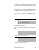
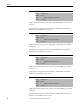
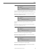
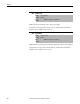
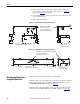
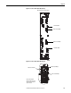
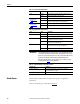
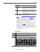
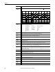
Table Of Contents
- Front Cover
- Important User Information
- Summary of Changes
- Table of Contents
- Introduction
- About the Drive
- Identifying the Drive by Cabinet Assembly ID Number
- LiquiFlo 2.0 Drive Component Locations
- Identifying the Power Module by Model Number
- AC Line I/O Board Description (Frame 3 Only)
- Standard I/O Board Description (Frame 3 Only)
- Combined I/O Board Description (Frame 4 Only)
- DPI Communication Ports
- Optional Equipment
- Planning the Installation
- Mounting The Power Module and Grounding the Drive
- Installing Input and Output Power Wiring
- Completing the Installation
- Using the Start-up Routines
- Programming Basics
- Parameter Descriptions
- Troubleshooting the Drive
- Verify that the DC Bus Capacitors are Discharged Before Servicing the Drive
- Determining Drive Status Using the Status LEDs
- About Alarms
- About Faults
- Diagnostic Parameters
- Common Symptoms and Corrective Actions
- Replacement Parts
- Board Replacement, Firmware Setup Procedures
- Troubleshooting the Drive Using the OIM
- Checking the Power Modules with Input Power Off
- Technical Specifications
- Using the OIM
- Installing and Removing the OIM
- Display Description
- OIM Menu Structure
- Powering Up and Adjusting the OIM
- Selecting a Device in the System
- Using the OIM to Program the Drive
- Monitoring the Drive Using the Process Display Screen on the OIM
- Displaying and Changing the OIM Reference
- Customizing the Process Display Screen
- Customizing the Function Keys
- Controlling the Drive From the OIM
- LiquiFlo 2.0 Drive Frame 3 Wiring Diagrams
- LiquiFlo 2.0 Drive Frame 4 Wiring Diagrams
- Index
- Back Cover

Rockwell Automation Publication D2-3518-3 - May 2013 199
Chapter 10
Table 18 - Types of Alarms
The drive indicates alarm conditions in the following ways:
• Status LEDs (see Determining Drive Status Using the Status LEDs
on
page 196).
• Alarm name and bell graphic on the OIM (see Appendix B
). The alarm
is displayed as long as the condition exists. The drive automatically clears
the alarm when the condition causing it is removed. The OIM only
displays alarm names for type 2 alarms, not for type 1 alarms. The bell
graphic appears for both type 1 and type 2 alarms.
• Alarm status parameters. Two 16-bit inverter parameters, Drive Alarm 1
(211) and Drive Alarm 2 (212), indicate the status of type 1 and type 2
alarms, respectively. See Chapter 9
for the parameter descriptions.
•Alarm queue. Alarms are placed into an alarm queue on the inverter as
they occur. The alarms in the queue do not have timestamps, and there is
no indication of when each alarm becomes inactive. The queue is visible
using the OIM and using VS Utilities. The alarm queue is separate from
the inverter fault queue.
Alarm Descriptions
Type Alarm Description
1
User-configurable These alarms alert the operator of conditions that, if left untreated, may
lead to a fault condition. The drive continues to operate during the alarm
condition.
The alarms are enabled or disabled using inverter Alarm Config 1 (259).
The status of these alarms is shown in inverter Drive Alarm 1 (211).
2
Non-configurable These alarms alert the operator of conditions caused by improper
programming and prevent the drive from starting until the problem is
resolved.
These alarms are always enabled.
The status of these alarms is shown in inverter Drive Alarm 2 (212).
Alarm
Type
Description
Analog In Loss 1 A user-configurable analog input is configured for alarm on signal loss and signal loss has occurred.
Bipolar
Conflict
2 Parameter inverter 190 (Direction Mode) is set to Bipolar or Reverse Dis and one of more of the following digital
input functions is configured: Fwd/Rev, Run Fwd, Run Rev, Jog Fwd, or Jog Rev.
Dig In
ConflictA
2 User-configurable digital input functions are in conflict. Combinations marked with a will cause an alarm.
Acc2 / Dec2 Accel 2 Decel 2 Jog Jog Fwd Jog Rev Fwd / Rev
Acc2 / Dec2
Accel 2
Decel 2
Jog
Jog Fwd
Jog Rev
Fwd / Rev