
Owner's manual
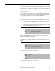
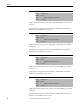
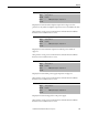
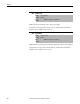
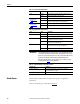
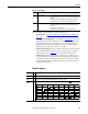
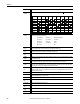
Table Of Contents
- Front Cover
- Important User Information
- Summary of Changes
- Table of Contents
- Introduction
- About the Drive
- Identifying the Drive by Cabinet Assembly ID Number
- LiquiFlo 2.0 Drive Component Locations
- Identifying the Power Module by Model Number
- AC Line I/O Board Description (Frame 3 Only)
- Standard I/O Board Description (Frame 3 Only)
- Combined I/O Board Description (Frame 4 Only)
- DPI Communication Ports
- Optional Equipment
- Planning the Installation
- Mounting The Power Module and Grounding the Drive
- Installing Input and Output Power Wiring
- Completing the Installation
- Using the Start-up Routines
- Programming Basics
- Parameter Descriptions
- Troubleshooting the Drive
- Verify that the DC Bus Capacitors are Discharged Before Servicing the Drive
- Determining Drive Status Using the Status LEDs
- About Alarms
- About Faults
- Diagnostic Parameters
- Common Symptoms and Corrective Actions
- Replacement Parts
- Board Replacement, Firmware Setup Procedures
- Troubleshooting the Drive Using the OIM
- Checking the Power Modules with Input Power Off
- Technical Specifications
- Using the OIM
- Installing and Removing the OIM
- Display Description
- OIM Menu Structure
- Powering Up and Adjusting the OIM
- Selecting a Device in the System
- Using the OIM to Program the Drive
- Monitoring the Drive Using the Process Display Screen on the OIM
- Displaying and Changing the OIM Reference
- Customizing the Process Display Screen
- Customizing the Function Keys
- Controlling the Drive From the OIM
- LiquiFlo 2.0 Drive Frame 3 Wiring Diagrams
- LiquiFlo 2.0 Drive Frame 4 Wiring Diagrams
- Index
- Back Cover
198 Rockwell Automation Publication D2-3518-3 - May 2013
Chapter 10
Table 15 - Inverter Status LED Definitions
Table 16 - Rectifier Status LED Definitions
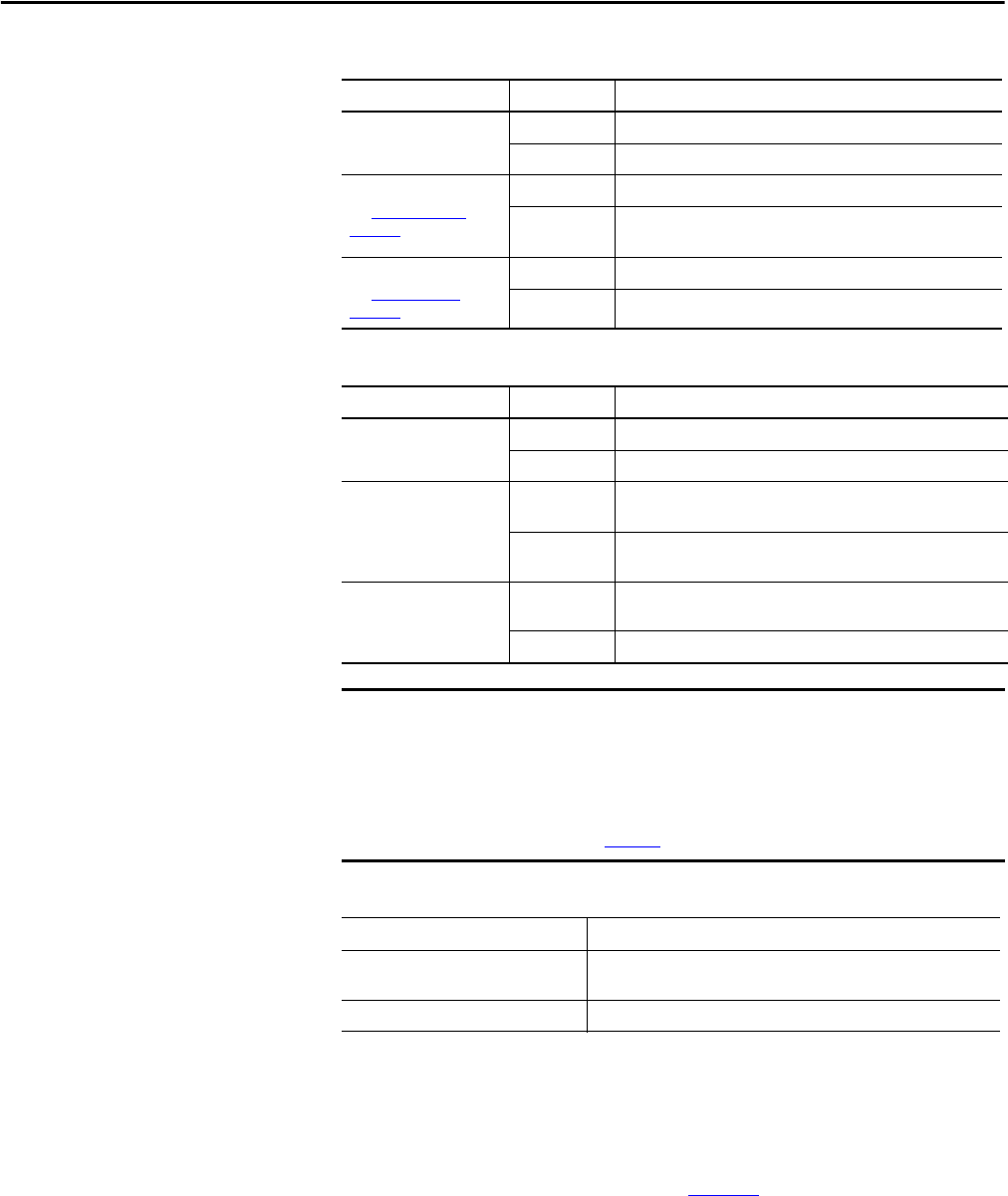
Table 17 - Status LED Definitions for Hardware Failure
About Alarms
Alarms indicate conditions that may affect drive operation or application
performance.
There are two alarm types, as described in Table 1 8
.
Color State Description
Green Flashing Drive ready, but not running and no faults or alarms are present.
Steady Drive running, no faults or alarms are present.
Yel lo w
See About Alarms on
page 198.
Flashing The drive is not ready. Check inverter parameter 214 (Start Inhibits).
Steady An alarm condition exists; drive may be running. Check inverter
parameters 211 (Drive Alarm 1) and 212 (Drive Alarm 2).
Red
See About Faults
on
page 201.
Flashing A fault has occurred.
Steady A non-resettable fault has occurred.
Color State Description
Green Flashing Rectifier ready, but not running and no faults are present.
Steady Rectifier running (providing current to inverter).
Yellow Flashing Precharge contactor is open and rectifier is not running. This is the
normal state if the inverter is not running.
Steady A rectifier alarm condition exists; rectifier may be running. Check
rectifier parameter 211 (Alarm Status).
Red Flashing A rectifier fault has occurred. This also causes an inverter fault, and
the fault is enunciated on the OIM or other DPI device.
Steady A non-resettable rectifier fault has occurred.
IMPORTANT
Certain hardware failures produce indications on the status LEDs that are not
covered in the above tables. For Frame 3 drives, the appropriate response to the
appearance of any of these indications is to replace either the Rectifier Control
board or Inverter Control board depending on which LED displays the
indication. For Frame 4 drives, the appropriate response is always to replace
the Control board. Table 17
lists the indications.
LED Indication Condition
Red/green alternating Control board boot firmware is running because control board
application firmware is corrupted.
Yellow/green/red repeating pattern Control board RAM has failed or control board boot firmware is corrupted.