
Owner's manual
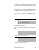
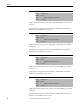
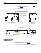
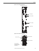
Table Of Contents
- Front Cover
- Important User Information
- Summary of Changes
- Table of Contents
- Introduction
- About the Drive
- Identifying the Drive by Cabinet Assembly ID Number
- LiquiFlo 2.0 Drive Component Locations
- Identifying the Power Module by Model Number
- AC Line I/O Board Description (Frame 3 Only)
- Standard I/O Board Description (Frame 3 Only)
- Combined I/O Board Description (Frame 4 Only)
- DPI Communication Ports
- Optional Equipment
- Planning the Installation
- Mounting The Power Module and Grounding the Drive
- Installing Input and Output Power Wiring
- Completing the Installation
- Using the Start-up Routines
- Programming Basics
- Parameter Descriptions
- Troubleshooting the Drive
- Verify that the DC Bus Capacitors are Discharged Before Servicing the Drive
- Determining Drive Status Using the Status LEDs
- About Alarms
- About Faults
- Diagnostic Parameters
- Common Symptoms and Corrective Actions
- Replacement Parts
- Board Replacement, Firmware Setup Procedures
- Troubleshooting the Drive Using the OIM
- Checking the Power Modules with Input Power Off
- Technical Specifications
- Using the OIM
- Installing and Removing the OIM
- Display Description
- OIM Menu Structure
- Powering Up and Adjusting the OIM
- Selecting a Device in the System
- Using the OIM to Program the Drive
- Monitoring the Drive Using the Process Display Screen on the OIM
- Displaying and Changing the OIM Reference
- Customizing the Process Display Screen
- Customizing the Function Keys
- Controlling the Drive From the OIM
- LiquiFlo 2.0 Drive Frame 3 Wiring Diagrams
- LiquiFlo 2.0 Drive Frame 4 Wiring Diagrams
- Index
- Back Cover
196 Rockwell Automation Publication D2-3518-3 - May 2013
Chapter 10
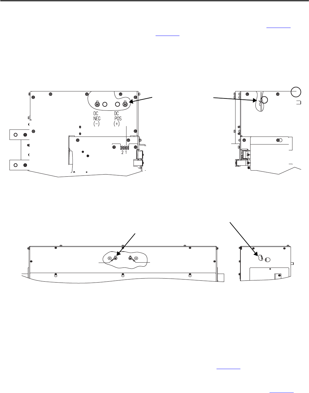
5. Measure the DC bus potential with a voltmeter while standing on a
non-conductive surface and wearing insulated gloves. See Figure 77
for
Frame 3, and Figure 78
for Frame 4.
6. Once the drive has been serviced, reattach the power module cover and
close the enclosure door.
7. Turn on the circuit breaker.
Figure 77 - Location of DC Bus Measuring Points (Frame 3)
Figure 78 - Location of DC Bus Measuring Points (Frame 4)
Determining Drive Status
Using the Status LEDs
The inverter and rectifier sections each have a status LED.
For Frame 3 drives, the status LEDs are located on the Communication Interface
board, and are labeled on the board itself as INV STATUS (inverter) and
ACTIVE RECT. STATUS (rectifier). See Figure 79
.
For Frame 4 drives, the status LEDs are located on the Control Board, and are
labeled on the board itself as B2 (inverter) and B1 (rectifier). See Figure 80
.
DC Bus measurement points on
laminated bus assembly.
0.25 in. x .032 in. male faston.
Accessible by removal of top cover.
Front View of Frame 3 Power Module
Right Side View of
Frame 3 Power Module
DC
POS.
(+)
DC
NEG.
(-)
Front View of Frame 4 Power Module Right Side View of
Frame 4 Power Module
DC Bus measurement points on laminated bus assembly.
0.25 in. x .032 in. male faston.
Accessible by removal of top cover.