
Owner's manual
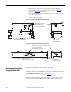
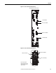
Table Of Contents
- Front Cover
- Important User Information
- Summary of Changes
- Table of Contents
- Introduction
- About the Drive
- Identifying the Drive by Cabinet Assembly ID Number
- LiquiFlo 2.0 Drive Component Locations
- Identifying the Power Module by Model Number
- AC Line I/O Board Description (Frame 3 Only)
- Standard I/O Board Description (Frame 3 Only)
- Combined I/O Board Description (Frame 4 Only)
- DPI Communication Ports
- Optional Equipment
- Planning the Installation
- Mounting The Power Module and Grounding the Drive
- Installing Input and Output Power Wiring
- Completing the Installation
- Using the Start-up Routines
- Programming Basics
- Parameter Descriptions
- Troubleshooting the Drive
- Verify that the DC Bus Capacitors are Discharged Before Servicing the Drive
- Determining Drive Status Using the Status LEDs
- About Alarms
- About Faults
- Diagnostic Parameters
- Common Symptoms and Corrective Actions
- Replacement Parts
- Board Replacement, Firmware Setup Procedures
- Troubleshooting the Drive Using the OIM
- Checking the Power Modules with Input Power Off
- Technical Specifications
- Using the OIM
- Installing and Removing the OIM
- Display Description
- OIM Menu Structure
- Powering Up and Adjusting the OIM
- Selecting a Device in the System
- Using the OIM to Program the Drive
- Monitoring the Drive Using the Process Display Screen on the OIM
- Displaying and Changing the OIM Reference
- Customizing the Process Display Screen
- Customizing the Function Keys
- Controlling the Drive From the OIM
- LiquiFlo 2.0 Drive Frame 3 Wiring Diagrams
- LiquiFlo 2.0 Drive Frame 4 Wiring Diagrams
- Index
- Back Cover
Rockwell Automation Publication D2-3518-3 - May 2013 195
Chapter 10
Troubleshooting the Drive
The LiquiFlo 2.0 AC drive provides the following ways to determine the status of
the drive and to troubleshoot problems that may occur:
• LEDs on the front of the drive
• User-configurable and non-configurable alarms
• User-configurable and non-configurable faults
• Entries in the fault queue
• Drive status parameters
Verify that the DC Bus
Capacitors are Discharged
Before Servicing the Drive
The DC bus capacitors of the drive retain hazardous voltages after input power
has been disconnected. Perform the following steps before touching any internal
components.
1. Turn off the circuit breaker and lock out input power. Wait 5 minutes.
2. Open the enclosure door to the power module.
3. Verify that there is no voltage at the power module’s input power terminals
(L1, L2, and L3) as shown in Figure 2 on page 15
for Frame 3, and Figure 5
on page 20 for Frame 4.
4. Remove the cover of the power module.
ATTENTION: Only qualified electrical personnel familiar with the construction
and operation of this equipment and the hazards involved should install, adjust,
operate, or service this equipment. Read and understand this manual and other
applicable manuals in their entirety before proceeding. Failure to observe this
precaution could result in severe bodily injury or loss of life.
ATTENTION: DC bus capacitors retain hazardous voltages after input power has
been disconnected. After disconnecting input power, wait 5 minutes for the DC
bus capacitors to discharge and then check the voltage with a voltmeter to
ensure the DC bus capacitors are discharged before touching any internal
components. Failure to observe this precaution could result in severe bodily
injury or loss of life.