
Owner's manual
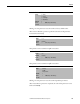
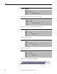
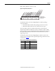
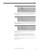
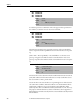
Table Of Contents
- Front Cover
- Important User Information
- Summary of Changes
- Table of Contents
- Introduction
- About the Drive
- Identifying the Drive by Cabinet Assembly ID Number
- LiquiFlo 2.0 Drive Component Locations
- Identifying the Power Module by Model Number
- AC Line I/O Board Description (Frame 3 Only)
- Standard I/O Board Description (Frame 3 Only)
- Combined I/O Board Description (Frame 4 Only)
- DPI Communication Ports
- Optional Equipment
- Planning the Installation
- Mounting The Power Module and Grounding the Drive
- Installing Input and Output Power Wiring
- Completing the Installation
- Using the Start-up Routines
- Programming Basics
- Parameter Descriptions
- Troubleshooting the Drive
- Verify that the DC Bus Capacitors are Discharged Before Servicing the Drive
- Determining Drive Status Using the Status LEDs
- About Alarms
- About Faults
- Diagnostic Parameters
- Common Symptoms and Corrective Actions
- Replacement Parts
- Board Replacement, Firmware Setup Procedures
- Troubleshooting the Drive Using the OIM
- Checking the Power Modules with Input Power Off
- Technical Specifications
- Using the OIM
- Installing and Removing the OIM
- Display Description
- OIM Menu Structure
- Powering Up and Adjusting the OIM
- Selecting a Device in the System
- Using the OIM to Program the Drive
- Monitoring the Drive Using the Process Display Screen on the OIM
- Displaying and Changing the OIM Reference
- Customizing the Process Display Screen
- Customizing the Function Keys
- Controlling the Drive From the OIM
- LiquiFlo 2.0 Drive Frame 3 Wiring Diagrams
- LiquiFlo 2.0 Drive Frame 4 Wiring Diagrams
- Index
- Back Cover

190 Rockwell Automation Publication D2-3518-3 - May 2013
Chapter 9
A code that represents a rectifier fault. The codes appear in these parameters in
the order they occur. Fault 1 Code = the most recent fault.
The time between initial power up and the occurrence of the associated fault.
Can be compared to Power Up Marker for the time from the most recent power
up.
(Fault x Time – Power Up Marker) = the time difference to the most recent
power up. A negative value indicates a fault occurred before the most recent
power up. A positive value indicates a fault occurred after the most recent power
up.
Amount of time used to determine whether rectifier Instantaneous Overcurrent
(IOC) fault redirection is discontinued because too many rectifier IOC events
have occurred in too short a period of time.
Certain AC line events cause the drive to stop running because of the detection
of a rectifier IOC condition. IOC fault redirection is a mechanism that allows
rectifier IOC conditions to be reported as Input Current Imbalance faults
(fault 225) rather than as rectifier IOC faults (rectifier faults 12, 211, 212, 213).
The purpose of this mechanism is to allow external drive control equipment to
distinguish between faults caused by AC line events and faults caused by internal
drive conditions.
243
245
247
249
Fault 1 Code
Fault 2 Code
Fault 3 Code
Fault 4 Code
Range: 0...65535
Default: Read Only
Access: 0 Path: Utility > Fault Queue
See also:
244
246
248
250
Fault 1 Time
Fault 2 Time
Fault 3 Time
Fault 4 Time
Range: 0.0000...429496.7295 [Hours]
Default: Read Only
Access: 0 Path: Utility > Fault Queue
See also:
300 IOC Redir Time
Range: 0...43200 minutes [30 days]
Default: 1440 minutes [24 hours]
Access: 0 Path: Communications > In Data Links
See also: 301