
Owner's manual

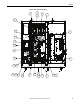
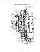
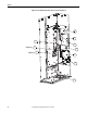
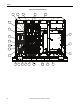
Table Of Contents
- Front Cover
- Important User Information
- Summary of Changes
- Table of Contents
- Introduction
- About the Drive
- Identifying the Drive by Cabinet Assembly ID Number
- LiquiFlo 2.0 Drive Component Locations
- Identifying the Power Module by Model Number
- AC Line I/O Board Description (Frame 3 Only)
- Standard I/O Board Description (Frame 3 Only)
- Combined I/O Board Description (Frame 4 Only)
- DPI Communication Ports
- Optional Equipment
- Planning the Installation
- Mounting The Power Module and Grounding the Drive
- Installing Input and Output Power Wiring
- Completing the Installation
- Using the Start-up Routines
- Programming Basics
- Parameter Descriptions
- Troubleshooting the Drive
- Verify that the DC Bus Capacitors are Discharged Before Servicing the Drive
- Determining Drive Status Using the Status LEDs
- About Alarms
- About Faults
- Diagnostic Parameters
- Common Symptoms and Corrective Actions
- Replacement Parts
- Board Replacement, Firmware Setup Procedures
- Troubleshooting the Drive Using the OIM
- Checking the Power Modules with Input Power Off
- Technical Specifications
- Using the OIM
- Installing and Removing the OIM
- Display Description
- OIM Menu Structure
- Powering Up and Adjusting the OIM
- Selecting a Device in the System
- Using the OIM to Program the Drive
- Monitoring the Drive Using the Process Display Screen on the OIM
- Displaying and Changing the OIM Reference
- Customizing the Process Display Screen
- Customizing the Function Keys
- Controlling the Drive From the OIM
- LiquiFlo 2.0 Drive Frame 3 Wiring Diagrams
- LiquiFlo 2.0 Drive Frame 4 Wiring Diagrams
- Index
- Back Cover

Rockwell Automation Publication D2-3518-3 - May 2013 19
Chapter 2
Drive Components Locations (Frame 4)
Frame 4 Units 180580-A07 and 180580-A09
The drive section contains the following main components. The numbered items
listed below correspond to the numbers used in Figure 5
. Replacement parts are
listed in Chapter 10
.
1. Circuit Breaker, 600V
2. Inductor
3. AC Contactor
4. Power Module Assembly
5. Input Filter Capacitor Assembly
6. OIM
7. Fans, 115V AC, Inductor (4)
8. Tra n sf o rm e r, 5 kVA
9. Fan, 115V AC, Contactor
10. Resistors, 100 kOhms, 50 W
11. Precharge Resistors
12. Relay, Oil Pump & Control Power Terminals
13. Fuse, Class RK-5, 600V, 10 A (2)
14. Fuse, Class CC, 600V, 25 A (1)
15. Fuse, Class CC, 600V, 10 A (1)
16. Fuse, Class T, 600V, 300 A (3)
17. Fuse, Class CC, 600V, 20 A (3)
18. Fuse, Class CC, 600V, 1 A (3)
19. Ground Lug, 2-600 MCM
20. Nameplate, Power Module
21. Door Inter-lock (2)
22. Surge Suppressor
23. Circuit Breaker Operating Mechanism