
Owner's manual
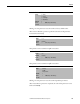
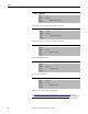
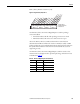
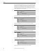
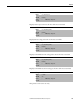
Table Of Contents
- Front Cover
- Important User Information
- Summary of Changes
- Table of Contents
- Introduction
- About the Drive
- Identifying the Drive by Cabinet Assembly ID Number
- LiquiFlo 2.0 Drive Component Locations
- Identifying the Power Module by Model Number
- AC Line I/O Board Description (Frame 3 Only)
- Standard I/O Board Description (Frame 3 Only)
- Combined I/O Board Description (Frame 4 Only)
- DPI Communication Ports
- Optional Equipment
- Planning the Installation
- Mounting The Power Module and Grounding the Drive
- Installing Input and Output Power Wiring
- Completing the Installation
- Using the Start-up Routines
- Programming Basics
- Parameter Descriptions
- Troubleshooting the Drive
- Verify that the DC Bus Capacitors are Discharged Before Servicing the Drive
- Determining Drive Status Using the Status LEDs
- About Alarms
- About Faults
- Diagnostic Parameters
- Common Symptoms and Corrective Actions
- Replacement Parts
- Board Replacement, Firmware Setup Procedures
- Troubleshooting the Drive Using the OIM
- Checking the Power Modules with Input Power Off
- Technical Specifications
- Using the OIM
- Installing and Removing the OIM
- Display Description
- OIM Menu Structure
- Powering Up and Adjusting the OIM
- Selecting a Device in the System
- Using the OIM to Program the Drive
- Monitoring the Drive Using the Process Display Screen on the OIM
- Displaying and Changing the OIM Reference
- Customizing the Process Display Screen
- Customizing the Function Keys
- Controlling the Drive From the OIM
- LiquiFlo 2.0 Drive Frame 3 Wiring Diagrams
- LiquiFlo 2.0 Drive Frame 4 Wiring Diagrams
- Index
- Back Cover

Rockwell Automation Publication D2-3518-3 - May 2013 189
Chapter 9
Faults in the rectifier may be cleared, and the fault queue cleared by writing to
this parameter. After the operation is completed, the value of this parameter will
revert to Ready (0).
This value is copied to the inverter through a datalink to transmit rectifier faults
to the inverter. This parameter is part of inverter/rectifier communications. Do
not write to this parameter.
Accumulated hours that the rectifier had been powered up at the time of the
most recent drive powerup.
This parameter is used along with the rectifier fault timestamp parameters
(Fault n Time parameters below[244, 246, 248, 250]) to determine whether a
rectifier fault in the rectifier fault queue happened before or after the most recent
drive powerup.
This value rolls over to 0 after the drive has been powered on for more than the
maximum value shown.
240 Fault Clear
Range: 0 = Ready
1 = Clear Faults
2 = Clear Flt Queue
Default: Read Only
Access: 0 Path: Utility > Fault Queue
See also:
241 Fault To Invertr
Range: 0...255
Default: Read Only
Access: 0 Path: Utility > Fault Queue
See also:
242 Power Up Marker
Range: 0.0000...429496.7295 [Hours]
Default: Read Only
Access: 0 Path: Utility > Fault Queue
See also: