
Owner's manual
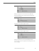
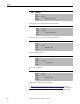
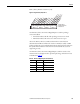
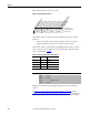
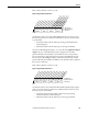
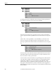
Table Of Contents
- Front Cover
- Important User Information
- Summary of Changes
- Table of Contents
- Introduction
- About the Drive
- Identifying the Drive by Cabinet Assembly ID Number
- LiquiFlo 2.0 Drive Component Locations
- Identifying the Power Module by Model Number
- AC Line I/O Board Description (Frame 3 Only)
- Standard I/O Board Description (Frame 3 Only)
- Combined I/O Board Description (Frame 4 Only)
- DPI Communication Ports
- Optional Equipment
- Planning the Installation
- Mounting The Power Module and Grounding the Drive
- Installing Input and Output Power Wiring
- Completing the Installation
- Using the Start-up Routines
- Programming Basics
- Parameter Descriptions
- Troubleshooting the Drive
- Verify that the DC Bus Capacitors are Discharged Before Servicing the Drive
- Determining Drive Status Using the Status LEDs
- About Alarms
- About Faults
- Diagnostic Parameters
- Common Symptoms and Corrective Actions
- Replacement Parts
- Board Replacement, Firmware Setup Procedures
- Troubleshooting the Drive Using the OIM
- Checking the Power Modules with Input Power Off
- Technical Specifications
- Using the OIM
- Installing and Removing the OIM
- Display Description
- OIM Menu Structure
- Powering Up and Adjusting the OIM
- Selecting a Device in the System
- Using the OIM to Program the Drive
- Monitoring the Drive Using the Process Display Screen on the OIM
- Displaying and Changing the OIM Reference
- Customizing the Process Display Screen
- Customizing the Function Keys
- Controlling the Drive From the OIM
- LiquiFlo 2.0 Drive Frame 3 Wiring Diagrams
- LiquiFlo 2.0 Drive Frame 4 Wiring Diagrams
- Index
- Back Cover

188 Rockwell Automation Publication D2-3518-3 - May 2013
Chapter 9
This parameter is for service use only.
This parameter is for service use only.
This parameter is for service use only.
Enables/disables annunciation of the faults shown in Figure 76
.
Figure 76 - Fault Config (238)
235 Testpoint 1 Data
Range: -/+ 217483646
Default: 0
Access: 0 Path: Utility > Diagnostics
See also:
236 Testpoint 2 Sel
Range: 0...65535
Default: 499
Access: 0 Path: Utility > Diagnostics
See also:
237 Testpoint 2 Data
Range: -/+ 217483646
Default: 0
Access: 0 Path: Utility > Diagnostics
See also:
238 Fault Config
Range: See Figure 76
Default: See Figure 76
Access: 0 Path: Utility > Fault Queue
See also:
0
xx
x
x
x
x
x
xxx
x
xxxx
0011234567891112131415
1=Enabled
0=Disabled
x =Reserved
Bit #
Factory Default Bit Values
Carrier Sync Loss
Nibble 1Nibble 2Nibble 3Nibble 4