
Owner's manual
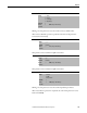
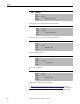
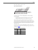
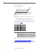
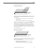
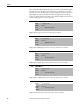
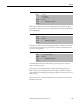
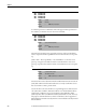
Table Of Contents
- Front Cover
- Important User Information
- Summary of Changes
- Table of Contents
- Introduction
- About the Drive
- Identifying the Drive by Cabinet Assembly ID Number
- LiquiFlo 2.0 Drive Component Locations
- Identifying the Power Module by Model Number
- AC Line I/O Board Description (Frame 3 Only)
- Standard I/O Board Description (Frame 3 Only)
- Combined I/O Board Description (Frame 4 Only)
- DPI Communication Ports
- Optional Equipment
- Planning the Installation
- Mounting The Power Module and Grounding the Drive
- Installing Input and Output Power Wiring
- Completing the Installation
- Using the Start-up Routines
- Programming Basics
- Parameter Descriptions
- Troubleshooting the Drive
- Verify that the DC Bus Capacitors are Discharged Before Servicing the Drive
- Determining Drive Status Using the Status LEDs
- About Alarms
- About Faults
- Diagnostic Parameters
- Common Symptoms and Corrective Actions
- Replacement Parts
- Board Replacement, Firmware Setup Procedures
- Troubleshooting the Drive Using the OIM
- Checking the Power Modules with Input Power Off
- Technical Specifications
- Using the OIM
- Installing and Removing the OIM
- Display Description
- OIM Menu Structure
- Powering Up and Adjusting the OIM
- Selecting a Device in the System
- Using the OIM to Program the Drive
- Monitoring the Drive Using the Process Display Screen on the OIM
- Displaying and Changing the OIM Reference
- Customizing the Process Display Screen
- Customizing the Function Keys
- Controlling the Drive From the OIM
- LiquiFlo 2.0 Drive Frame 3 Wiring Diagrams
- LiquiFlo 2.0 Drive Frame 4 Wiring Diagrams
- Index
- Back Cover
Rockwell Automation Publication D2-3518-3 - May 2013 185
Chapter 9
Frame 3 drives (firmware version 1.x) only:
Figure 74 - Dig Out Status (217) Frame 3
On the Frame 3 drive, AC Line I/O Board Digital Output 1 is used to control
the shunt trip, and various conditions inside the drive can cause the shunt trip to
be commanded.
• A 1 in bit 0 indicates that the shunt trip is being commanded (breaker
commanded open).
• A 0 in bit 0 indicates that the shunt trip is not being commanded.
AC Line I/O Board Digital Outputs 1...6 are also called the application digital
outputs. They are commanded by the inverter using bits 0...5 of rectifier
parameter Rectifier Contrl (100), but you should not write to this parameter.
You can control these outputs using inverter parameter Appl Digital Out (30).
For AC Line I/O Board Digital Output 1, this shunt trip control via rectifier
parameter Rectifier Contrl (100) is in addition to the internal rectifier conditions
that can cause a shunt trip.
Frame 4 drives (firmware version 2.x) only:
Figure 75 - Dig Out Status (217) Frame 4
On the Frame 4 drive, the Combined I/O Board dedicated Shunt Trip output is
used to control the shunt trip, and various conditions inside the drive can cause
the shunt trip to be commanded.
• A 1 in bit 0 of this parameter indicates that the shunt trip is being
commanded (breaker commanded open).
• A 0 in bit 0 indicates that the shunt trip is not being commanded.
0000xxxx
x
x
x
x
x
x
0011234567891112131415
1=Input Active
0
00
=Input Not Active
x =Reserved
Bit #
AC Line I/O: Dig. Output 1
AC Line I/O: Dig. Output 2
AC Line I/O: Dig. Output 3
AC Line I/O: Dig. Output 4
AC Line I/O: Dig. Output 5
AC Line I/O: Dig. Output 6
Nibble 1Nibble 2Nibble 3Nibble 4
0xxxx
x
x
x
x
xxx
x
x
x
x
0011234567891112131415
1=Input Active
0=Input Not Active
x =Reserved
Bit #
Shunt Trip
Nibble 1Nibble 2Nibble 3Nibble 4