
Owner's manual
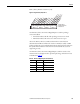
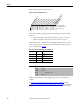
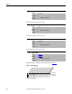
Table Of Contents
- Front Cover
- Important User Information
- Summary of Changes
- Table of Contents
- Introduction
- About the Drive
- Identifying the Drive by Cabinet Assembly ID Number
- LiquiFlo 2.0 Drive Component Locations
- Identifying the Power Module by Model Number
- AC Line I/O Board Description (Frame 3 Only)
- Standard I/O Board Description (Frame 3 Only)
- Combined I/O Board Description (Frame 4 Only)
- DPI Communication Ports
- Optional Equipment
- Planning the Installation
- Mounting The Power Module and Grounding the Drive
- Installing Input and Output Power Wiring
- Completing the Installation
- Using the Start-up Routines
- Programming Basics
- Parameter Descriptions
- Troubleshooting the Drive
- Verify that the DC Bus Capacitors are Discharged Before Servicing the Drive
- Determining Drive Status Using the Status LEDs
- About Alarms
- About Faults
- Diagnostic Parameters
- Common Symptoms and Corrective Actions
- Replacement Parts
- Board Replacement, Firmware Setup Procedures
- Troubleshooting the Drive Using the OIM
- Checking the Power Modules with Input Power Off
- Technical Specifications
- Using the OIM
- Installing and Removing the OIM
- Display Description
- OIM Menu Structure
- Powering Up and Adjusting the OIM
- Selecting a Device in the System
- Using the OIM to Program the Drive
- Monitoring the Drive Using the Process Display Screen on the OIM
- Displaying and Changing the OIM Reference
- Customizing the Process Display Screen
- Customizing the Function Keys
- Controlling the Drive From the OIM
- LiquiFlo 2.0 Drive Frame 3 Wiring Diagrams
- LiquiFlo 2.0 Drive Frame 4 Wiring Diagrams
- Index
- Back Cover
184 Rockwell Automation Publication D2-3518-3 - May 2013
Chapter 9
Frame 4 drives (firmware version 2.x) only:
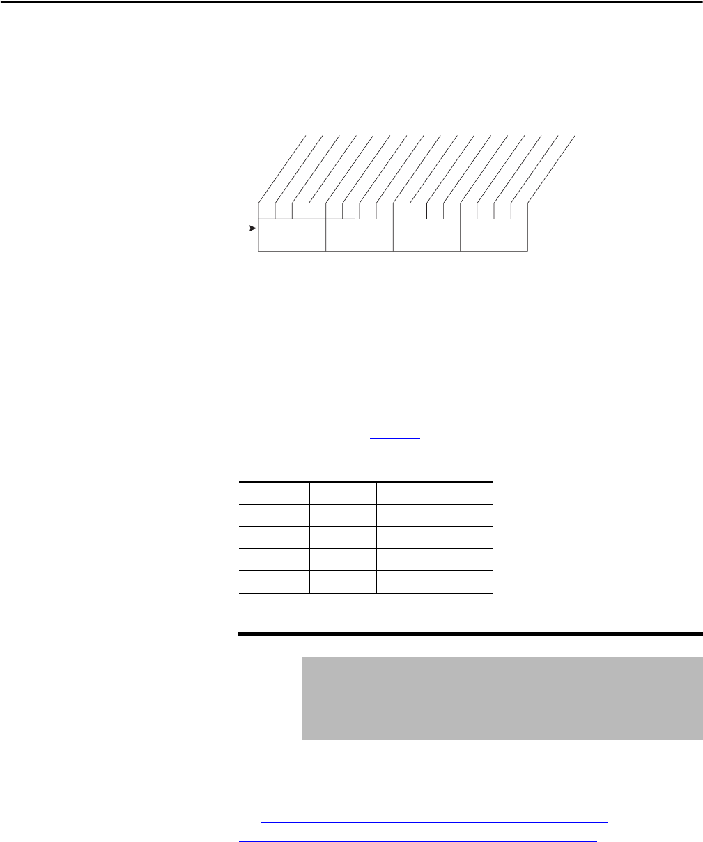
Figure 73 - Dig In Status (216) Frame 4
On the Frame 4 drive, precharge contactor feedback appears in bit 15 of this
parameter.
• A 1 in bit 15 indicates that all of the precharge contactors are closed.
• A 0 in bit 15 indicates that at least one of the contactors is open.
On the Frame 4 drive, Combined I/O board Digital Inputs 1 and 2 are used to
select measurements to be displayed on the optional input voltage and current
meters, as described in Tab le 1 4
.
Table 14 - AC Line I/O Digital Inputs 3 and 4 (Frame 4)
Displays commanded status of the digital outputs that are controlled by the
rectifier.
See AC Line I/O Board Description (Frame 3 Only)
on page 25 through
Combined I/O Board Description (Frame 4 Only)
on page 29 for a description
of I/O hardware that is present on this drive and is controlled by the rectifier.
Dig. In 2 Dig. In 1 Selected Measurement
0 0 Iv, Vst
0 1 Iw, Vtr
1 0 Iu, Vrs
1 1 Iu, Vrs
217 Dig Out Status
Range: Bits on/off
Default: Read Only
Access: 0 Path: Utility > Status
See also: inverter 30
0
0xxx
xx
x
xxxx
x
xx
0011234567891112131415
1=Input Active
0
0
=Input Not Active
x =Reserved
Bit #
Combined I/O Dig. Input 1
Combined I/O Dig. Input 2
Precharge Feedback
Nibble 1Nibble 2Nibble 3Nibble 4