
Owner's manual
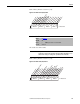
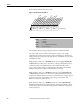
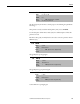
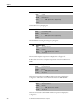
Table Of Contents
- Front Cover
- Important User Information
- Summary of Changes
- Table of Contents
- Introduction
- About the Drive
- Identifying the Drive by Cabinet Assembly ID Number
- LiquiFlo 2.0 Drive Component Locations
- Identifying the Power Module by Model Number
- AC Line I/O Board Description (Frame 3 Only)
- Standard I/O Board Description (Frame 3 Only)
- Combined I/O Board Description (Frame 4 Only)
- DPI Communication Ports
- Optional Equipment
- Planning the Installation
- Mounting The Power Module and Grounding the Drive
- Installing Input and Output Power Wiring
- Completing the Installation
- Using the Start-up Routines
- Programming Basics
- Parameter Descriptions
- Troubleshooting the Drive
- Verify that the DC Bus Capacitors are Discharged Before Servicing the Drive
- Determining Drive Status Using the Status LEDs
- About Alarms
- About Faults
- Diagnostic Parameters
- Common Symptoms and Corrective Actions
- Replacement Parts
- Board Replacement, Firmware Setup Procedures
- Troubleshooting the Drive Using the OIM
- Checking the Power Modules with Input Power Off
- Technical Specifications
- Using the OIM
- Installing and Removing the OIM
- Display Description
- OIM Menu Structure
- Powering Up and Adjusting the OIM
- Selecting a Device in the System
- Using the OIM to Program the Drive
- Monitoring the Drive Using the Process Display Screen on the OIM
- Displaying and Changing the OIM Reference
- Customizing the Process Display Screen
- Customizing the Function Keys
- Controlling the Drive From the OIM
- LiquiFlo 2.0 Drive Frame 3 Wiring Diagrams
- LiquiFlo 2.0 Drive Frame 4 Wiring Diagrams
- Index
- Back Cover
172 Rockwell Automation Publication D2-3518-3 - May 2013
Chapter 9
Frame 4 drives (firmware version 2.x) only:
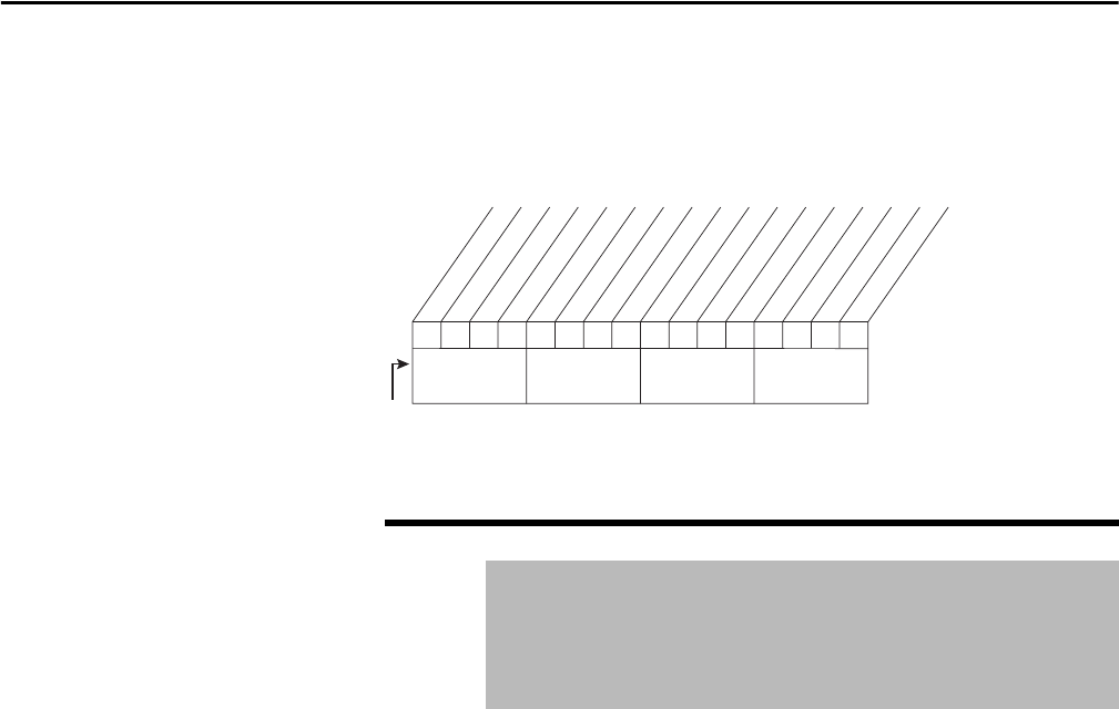
Figure 71 - Rectifier Status (101) Frame 4
Selects whether DC bus voltage (Vdc) optimization is enabled or disabled.
At low speeds the inverter requires a lower DC bus voltage, so the voltage
supplied by the rectifier can be lowered to reduce switching losses. The DC bus
voltage must be greater than the peak of the AC line, so this feature is more useful
with 400V AC input.
If Vdc Optimize (102) is set to Disabled, the DC bus voltage generated by the
rectifier while the rectifier or the entire drive is running is calculated based on a
combination of the value of Vdc Reference (103) and measured line-to-line
voltage of the AC line. In this case, Vdc Reference (103) defines the minimum
DC bus voltage that the rectifier commands while it is running.
If Vdc Optimize (102) is set to Enabled, the DC bus voltage generated by the
rectifier while the rectifier or the entire drive is running is calculated based on a
combination of the DC bus level necessary to provide the motor voltage required
by the inverter and the measured line-to-line voltage of the AC line. Vdc
Reference (103) is not used in this case.
If Vdc Optimize (102) is set to Enabled, the DC bus voltage required by the
inverter is calculated from the output frequency of the inverter and the value of
the Max Motor Volts (107), Max Motor Freq (108), and Base Motor Freq (109)
rectifier parameters.
102 Vdc Optimize
Range: 0 = Disabled
1 = Enabled
Default: 0 = Disabled
Access: 0 Dynamic Control > Bus Voltage
See also: 103, 104, 107, 108, 109
x
0011234567891112131415
x =Reserved
Bit #
OK to Run Inverter
Rectifier Running
Rectifier Faulted
Rectifier in Limit
Rectifier Synchronized
Rectifier Phased ACB
Rectifier at Voltage
Rectifier Regenerating
Fault Reset Echo
Nibble 1Nibble 2Nibble 3Nibble 4
Rectifier Carrier Sync
Loop Control Enable
Appl. Digital Out 3
Bit 0 indicates OK to run
Appl. Digital Out 4
Standby