
Owner's manual

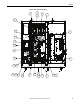
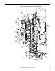
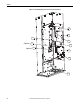
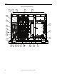
Table Of Contents
- Front Cover
- Important User Information
- Summary of Changes
- Table of Contents
- Introduction
- About the Drive
- Identifying the Drive by Cabinet Assembly ID Number
- LiquiFlo 2.0 Drive Component Locations
- Identifying the Power Module by Model Number
- AC Line I/O Board Description (Frame 3 Only)
- Standard I/O Board Description (Frame 3 Only)
- Combined I/O Board Description (Frame 4 Only)
- DPI Communication Ports
- Optional Equipment
- Planning the Installation
- Mounting The Power Module and Grounding the Drive
- Installing Input and Output Power Wiring
- Completing the Installation
- Using the Start-up Routines
- Programming Basics
- Parameter Descriptions
- Troubleshooting the Drive
- Verify that the DC Bus Capacitors are Discharged Before Servicing the Drive
- Determining Drive Status Using the Status LEDs
- About Alarms
- About Faults
- Diagnostic Parameters
- Common Symptoms and Corrective Actions
- Replacement Parts
- Board Replacement, Firmware Setup Procedures
- Troubleshooting the Drive Using the OIM
- Checking the Power Modules with Input Power Off
- Technical Specifications
- Using the OIM
- Installing and Removing the OIM
- Display Description
- OIM Menu Structure
- Powering Up and Adjusting the OIM
- Selecting a Device in the System
- Using the OIM to Program the Drive
- Monitoring the Drive Using the Process Display Screen on the OIM
- Displaying and Changing the OIM Reference
- Customizing the Process Display Screen
- Customizing the Function Keys
- Controlling the Drive From the OIM
- LiquiFlo 2.0 Drive Frame 3 Wiring Diagrams
- LiquiFlo 2.0 Drive Frame 4 Wiring Diagrams
- Index
- Back Cover

16 Rockwell Automation Publication D2-3518-3 - May 2013
Chapter 2
Power Module Components Locations (Frame 3)
Frame 3 Units LF200460AAR and LF200608CCR
The power module section contains the following main components. The
numbered items listed below correspond to the numbers used in Figure 3
and
Figure 4
. Replacement parts are listed in Chapter 10.
1. Wire Harness Assembly, Power Supply, Logic (2)
2. Current Feedback Device, 1000 A (6)
3. Terminal Block, 2-Position
4. 80 W Power Supply Assembly (2)
5. Cable Assembly, 40-pin, 0.050 in Pitch, Flex Film (2)
6. Cable Assembly, 30-pin, 0.050 in Pitch, Flex Film (2)
7. Wire Harness Assembly, Power Supply, Upper Gate (2)
8. Inverter Power Interface Assembly
9. Wire Harness Assembly, Power Supply, Lower Gate (2)
10. Insulation Sheet (2)
11. Communications Interface Assembly
12. Rectifier Power Interface Assembly
13. Wire Harness Assembly, Gate Driver
14. Wire Harness Assembly, Current Feedback Device
15. Wire Harness Assembly, Line Sync.
16. Wire Harness Assembly, DC Bus Bleeder Resistors
17. Cable Assembly, 20-pin, 0.050 in Pitch, Flex Film (optional)
18. Communications Assembly (optional)
19. Internal Fan
20. Connector, Terminal Block, 32-pin
21. AC Line I/O Assembly
22. Rectifier Control Assembly
23. Inverter Control Assembly
24. Standard I/O Assembly
25. Wire Harness Assembly, Control Sync.