
Owner's manual
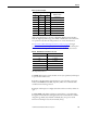
Table Of Contents
- Front Cover
- Important User Information
- Summary of Changes
- Table of Contents
- Introduction
- About the Drive
- Identifying the Drive by Cabinet Assembly ID Number
- LiquiFlo 2.0 Drive Component Locations
- Identifying the Power Module by Model Number
- AC Line I/O Board Description (Frame 3 Only)
- Standard I/O Board Description (Frame 3 Only)
- Combined I/O Board Description (Frame 4 Only)
- DPI Communication Ports
- Optional Equipment
- Planning the Installation
- Mounting The Power Module and Grounding the Drive
- Installing Input and Output Power Wiring
- Completing the Installation
- Using the Start-up Routines
- Programming Basics
- Parameter Descriptions
- Troubleshooting the Drive
- Verify that the DC Bus Capacitors are Discharged Before Servicing the Drive
- Determining Drive Status Using the Status LEDs
- About Alarms
- About Faults
- Diagnostic Parameters
- Common Symptoms and Corrective Actions
- Replacement Parts
- Board Replacement, Firmware Setup Procedures
- Troubleshooting the Drive Using the OIM
- Checking the Power Modules with Input Power Off
- Technical Specifications
- Using the OIM
- Installing and Removing the OIM
- Display Description
- OIM Menu Structure
- Powering Up and Adjusting the OIM
- Selecting a Device in the System
- Using the OIM to Program the Drive
- Monitoring the Drive Using the Process Display Screen on the OIM
- Displaying and Changing the OIM Reference
- Customizing the Process Display Screen
- Customizing the Function Keys
- Controlling the Drive From the OIM
- LiquiFlo 2.0 Drive Frame 3 Wiring Diagrams
- LiquiFlo 2.0 Drive Frame 4 Wiring Diagrams
- Index
- Back Cover

Rockwell Automation Publication D2-3518-3 - May 2013 159
Chapter 9
Selects the drive status that will energize user-configurable digital output 1.
See AC Line I/O Board Description (Frame 3 Only)
on page 25 through
Combined I/O Board Description (Frame 4 Only)
on page 29 for a description
of I/O hardware that is present on this drive and is controlled by the inverter.
For Frame 3 drives (firmware version 1.x), most of the values possible for this
parameter only affect the operation of the drive if an optional Standard I/O
board is present.
The only exception is when Dig Out1 Sel (380) is set to Aux Run (28). If the
parameter is set to Aux Run (28), digital output 2 on the AC Line I/O board is
energized whenever the inverter is running, even if an optional Standard I/O
board is not present.
380 Digital Out1 Sel
Range: 1 = Fault (De-energized = Fault, Energized = No Fault)
2 = Alarm (De-energized = Inverter Alarm, Energized = No Inverter Alarm)
3 = Ready
4 = Run
5 = Forward Run
6 = Reverse Run
7 = Auto Restart
8 = Powerup Run
9 = At Speed
10 = At Freq
11 = At Current
12 = At Torque
13 = At Temp
14 = At Bus Volts
15 = At PI Error
16 = DC Braking
17 = Curr Limit
18 = Economize
19 = Motor Overld
20 = Power Loss
21 = Input 1 Link
22 = Input 2 Link
23 = Input 3 Link
24 = Input 4 Link
25 = Input 5 Link
26 = Input 6 Link
27 = Shunt Trip
28 = Aux Run
Default: 27 = Shunt Trip
Access: 0 Path: Inputs & Outputs > Digital Outputs
See also: 1...4, 12, 48, 53, 137, 147, 157, 184, 218, 381...383, 385, 386