
Owner's manual
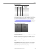
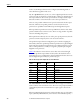
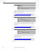
Table Of Contents
- Front Cover
- Important User Information
- Summary of Changes
- Table of Contents
- Introduction
- About the Drive
- Identifying the Drive by Cabinet Assembly ID Number
- LiquiFlo 2.0 Drive Component Locations
- Identifying the Power Module by Model Number
- AC Line I/O Board Description (Frame 3 Only)
- Standard I/O Board Description (Frame 3 Only)
- Combined I/O Board Description (Frame 4 Only)
- DPI Communication Ports
- Optional Equipment
- Planning the Installation
- Mounting The Power Module and Grounding the Drive
- Installing Input and Output Power Wiring
- Completing the Installation
- Using the Start-up Routines
- Programming Basics
- Parameter Descriptions
- Troubleshooting the Drive
- Verify that the DC Bus Capacitors are Discharged Before Servicing the Drive
- Determining Drive Status Using the Status LEDs
- About Alarms
- About Faults
- Diagnostic Parameters
- Common Symptoms and Corrective Actions
- Replacement Parts
- Board Replacement, Firmware Setup Procedures
- Troubleshooting the Drive Using the OIM
- Checking the Power Modules with Input Power Off
- Technical Specifications
- Using the OIM
- Installing and Removing the OIM
- Display Description
- OIM Menu Structure
- Powering Up and Adjusting the OIM
- Selecting a Device in the System
- Using the OIM to Program the Drive
- Monitoring the Drive Using the Process Display Screen on the OIM
- Displaying and Changing the OIM Reference
- Customizing the Process Display Screen
- Customizing the Function Keys
- Controlling the Drive From the OIM
- LiquiFlo 2.0 Drive Frame 3 Wiring Diagrams
- LiquiFlo 2.0 Drive Frame 4 Wiring Diagrams
- Index
- Back Cover

156 Rockwell Automation Publication D2-3518-3 - May 2013
Chapter 9
mode to use. If this input function is not configured, then Bus Reg Mode A
selects which bus regulation mode to use.
15...17 = Speed Select 1, 2, 3: One, two, or three digital input functions can be
used to select the speed reference used by the drive, and they are called the Speed
Select input functions. The current open/closed state of all Speed Select input
functions combine to select which source is the current speed reference.
There are seven possible combinations of open/closed states for the three input
functions, and thus seven possible parameters can be selected. The seven
parameters are: Speed Ref A Sel and Preset Speed 2 through Preset Speed 7.
If the Speed Select input functions select Speed Ref A Sel, then the value of that
parameter further selects a reference source. There are a large number of possible
selections, including all six presets.
If the input functions directly select one of the preset speed parameters, then the
parameter contains a frequency that is to be used as the reference.
The Speed Select input function configuration process involves assigning the
functionality of the three possible Speed Select input functions to physical digital
inputs. The three Speed Select inputs functions are called Speed Select 1, Speed
Select 2, and Speed Select 3, and they are assigned to physical inputs using the
Digital In“x” Sel parameters.
Tab le 1 2
describes the various reference sources that can be selected using all
three of the Speed Select input functions. If any of the three Reference Select
input functions are not configured, the software still follows the table, but treats
the unconfigured inputs as if they are permanently open.
Table 12 - Effect of Speed Select Input State on Selected Reference
18 = Auto/Manual: The Auto/Manual function allows a single control device to
assume exclusive control of reference select. The most recent peripheral (OIM or
terminal block) that makes a manual reference request is given control of the
reference.
If the Auto/Manual input function is closed, then the drive uses one of the analog
inputs (defined by TB Man Ref Sel) as the reference. If an OIM subsequently
Speed
Select 3
Speed
Select 2
Speed
Select 1
Parameter that determines reference:
Open Open Open Speed Ref A Sel
Open Open Closed Speed Ref B Sel
Open Closed Open Preset Speed 2
Open Closed Closed Preset Speed 3
Closed Open Open Preset Speed 4
Closed Open Closed Preset Speed 5
Closed Closed Open Preset Speed 6
Closed Closed Closed Preset Speed 7