
Owner's manual
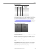
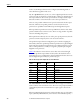
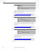
Table Of Contents
- Front Cover
- Important User Information
- Summary of Changes
- Table of Contents
- Introduction
- About the Drive
- Identifying the Drive by Cabinet Assembly ID Number
- LiquiFlo 2.0 Drive Component Locations
- Identifying the Power Module by Model Number
- AC Line I/O Board Description (Frame 3 Only)
- Standard I/O Board Description (Frame 3 Only)
- Combined I/O Board Description (Frame 4 Only)
- DPI Communication Ports
- Optional Equipment
- Planning the Installation
- Mounting The Power Module and Grounding the Drive
- Installing Input and Output Power Wiring
- Completing the Installation
- Using the Start-up Routines
- Programming Basics
- Parameter Descriptions
- Troubleshooting the Drive
- Verify that the DC Bus Capacitors are Discharged Before Servicing the Drive
- Determining Drive Status Using the Status LEDs
- About Alarms
- About Faults
- Diagnostic Parameters
- Common Symptoms and Corrective Actions
- Replacement Parts
- Board Replacement, Firmware Setup Procedures
- Troubleshooting the Drive Using the OIM
- Checking the Power Modules with Input Power Off
- Technical Specifications
- Using the OIM
- Installing and Removing the OIM
- Display Description
- OIM Menu Structure
- Powering Up and Adjusting the OIM
- Selecting a Device in the System
- Using the OIM to Program the Drive
- Monitoring the Drive Using the Process Display Screen on the OIM
- Displaying and Changing the OIM Reference
- Customizing the Process Display Screen
- Customizing the Function Keys
- Controlling the Drive From the OIM
- LiquiFlo 2.0 Drive Frame 3 Wiring Diagrams
- LiquiFlo 2.0 Drive Frame 4 Wiring Diagrams
- Index
- Back Cover

152 Rockwell Automation Publication D2-3518-3 - May 2013
Chapter 9
361
362
363
364
365
366
Digital In1 Sel
Digital In2 Sel
Digital In3 Sel
Digital In4 Sel
Digital In5 Sel
Digital In6 Sel
Range: 0 = Not Used
1 = Enable
2 = Clear Faults
(1)
3 = Aux Fault
4 = Stop - CF
(2)
5 = Start
6 = Fwd/Reverse
2
7 = Run
(3)
8 = Run Forward
3
9 = Run Reverse
3
10 = Jog
11 = Jog Forward
12 = Jog Reverse
13 = Stop Mode B
14 = Bus Reg Md B
15 = Speed Sel 1
(4)
16 = Speed Sel 2
4
17 = Speed Sel 3
4
18 = Auto/Manual
19 = Local
20 = Acc2 & Dec2
21 = Accel 2
22 = Decel 2
23 = MOP Inc
24 = MOP Dec
25 = Excl Link
26 = PI Enable
27 = PI Hold
28 = PI Reset
29 = Pwr Loss Lvl
30 = Precharge En
(1) When Digital In”x” Sel is set to option 2 (Clear Faults), the stop key cannot be used to clear a fault condition.
(2) Typical 3-Wire Inputs. These require that only 3-wire functions are chosen. Including 2-wire selections causes a type 2 alarm.
(3) Typical 2-Wire Inputs. These require that only 2-wire functions are chosen. Including 3-wire selections causes a type 2 alarm.
(4) To access Preset Speed 1, set Speed Ref A Sel to Preset Speed 1. See Tab le 9
.
Default: See Table 10
Access: 361...366 = 0 Path: Inputs & Outputs > Digital Inputs
See also: 96, 100, 124, 140, 156, 162, 194, 380