
Owner's manual
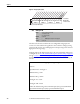
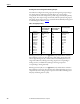
Table Of Contents
- Front Cover
- Important User Information
- Summary of Changes
- Table of Contents
- Introduction
- About the Drive
- Identifying the Drive by Cabinet Assembly ID Number
- LiquiFlo 2.0 Drive Component Locations
- Identifying the Power Module by Model Number
- AC Line I/O Board Description (Frame 3 Only)
- Standard I/O Board Description (Frame 3 Only)
- Combined I/O Board Description (Frame 4 Only)
- DPI Communication Ports
- Optional Equipment
- Planning the Installation
- Mounting The Power Module and Grounding the Drive
- Installing Input and Output Power Wiring
- Completing the Installation
- Using the Start-up Routines
- Programming Basics
- Parameter Descriptions
- Troubleshooting the Drive
- Verify that the DC Bus Capacitors are Discharged Before Servicing the Drive
- Determining Drive Status Using the Status LEDs
- About Alarms
- About Faults
- Diagnostic Parameters
- Common Symptoms and Corrective Actions
- Replacement Parts
- Board Replacement, Firmware Setup Procedures
- Troubleshooting the Drive Using the OIM
- Checking the Power Modules with Input Power Off
- Technical Specifications
- Using the OIM
- Installing and Removing the OIM
- Display Description
- OIM Menu Structure
- Powering Up and Adjusting the OIM
- Selecting a Device in the System
- Using the OIM to Program the Drive
- Monitoring the Drive Using the Process Display Screen on the OIM
- Displaying and Changing the OIM Reference
- Customizing the Process Display Screen
- Customizing the Function Keys
- Controlling the Drive From the OIM
- LiquiFlo 2.0 Drive Frame 3 Wiring Diagrams
- LiquiFlo 2.0 Drive Frame 4 Wiring Diagrams
- Index
- Back Cover
148 Rockwell Automation Publication D2-3518-3 - May 2013
Chapter 9
Scaling the User-configurable Analog Output
You define the scaling for the analog output by entering analog output voltages
into Analog Out1 Lo and Analog Out1 Hi. These two output voltages
correspond to the bottom and top of the possible range covered by the quantity
being output. The output voltage varies linearly with the quantity being output.
The analog output voltage does not go outside the limits defined by Analog Out1
Lo and Analog Out 1 Hi. See Ta b le 8
.
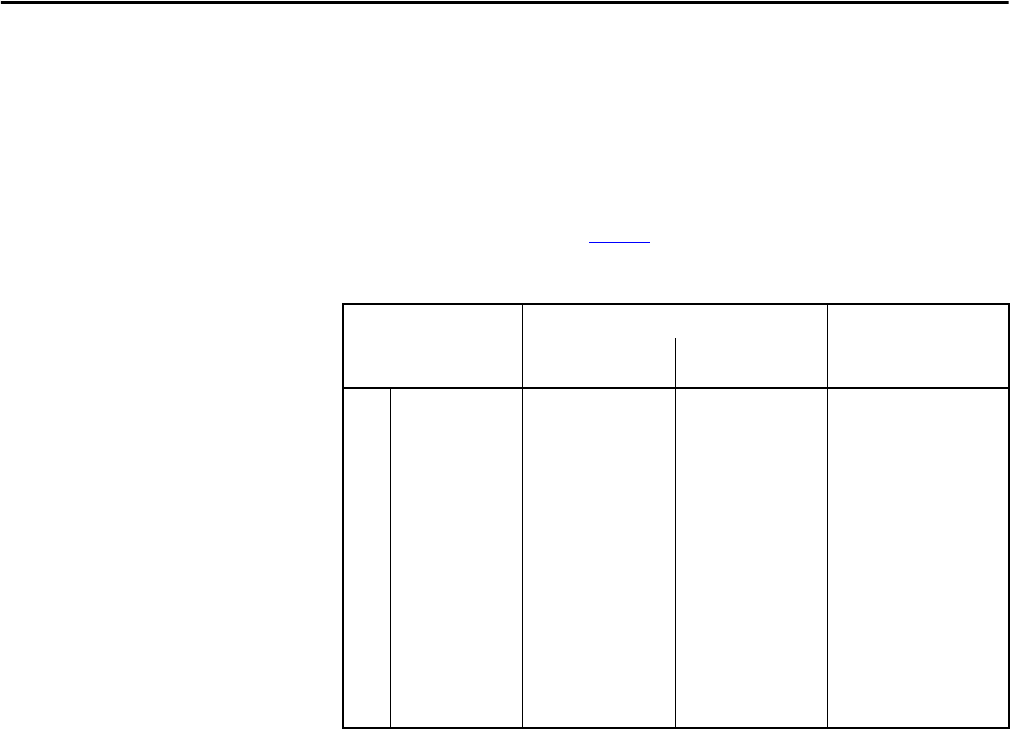
Table 8 - Analog Output Scaling
If Analog Out1 Sel (342) is set to Application (14), and the drive is a Frame 3
drive (firmware version 1.x), then the source of the analog output value is the
value in Appl Analog Out (31), and the values entered in that parameter can
range from 4.000 mA (resulting in an analog output level corresponding to
Analog Out1 Lo) to 20.000 mA (resulting in an analog output level
corresponding to Analog Out1 Hi).
If Analog Out1 Sel (342) is set to Application (14), and the drive is a Frame 4
drive (firmware version 2.x), then the value entered in Appl Analog Out (31) is
output directly on the analog output, irrespective of the values of Analog Out1
Hi (343) and Analog Out1 Lo (344).
Options Analog Out1 Lo Value Corresponds to: Analog Out 1 Hi (343)
Value Corresponds to:
Analog Out Absolut
(341) = Disabled
Analog Out Absolut
(341) = Enabled
0
1
2
3
4
5
6
7
8
9
10
11
12
13
14
Output Freq
Commanded Freq
Output Amps
Torque Amps
Flux Amps
Output Power
Output Volts
DC Bus Volts
PI Reference
PI Feedback
PI Error
PI Output
%Motor OL
%Drive OL
Application
–[Maximum Freq]
–[Maximum Speed]
0 Amps
–200% Rated
0 Amps
0 kW
0 Volts
0 Volts
–100%
–100%
–100%
–100%
0%
0%
see below
0 Hz
0 Hz
0 Amps
0 Amps
0 Amps
0 kW
0 Volts
0 Volts
0%
0%
0%
0%
0%
0%
see below
+[Maximum Freq]
+[Maximum Speed]
200% Rated
200% Rated
200% Rated
200% Rated
120% Rated
200% Rated
100%
100%
100%
100%
100%
100%
see below