
Owner's manual
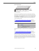
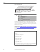
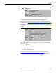
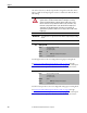
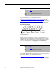
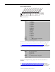
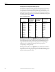
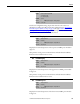
Table Of Contents
- Front Cover
- Important User Information
- Summary of Changes
- Table of Contents
- Introduction
- About the Drive
- Identifying the Drive by Cabinet Assembly ID Number
- LiquiFlo 2.0 Drive Component Locations
- Identifying the Power Module by Model Number
- AC Line I/O Board Description (Frame 3 Only)
- Standard I/O Board Description (Frame 3 Only)
- Combined I/O Board Description (Frame 4 Only)
- DPI Communication Ports
- Optional Equipment
- Planning the Installation
- Mounting The Power Module and Grounding the Drive
- Installing Input and Output Power Wiring
- Completing the Installation
- Using the Start-up Routines
- Programming Basics
- Parameter Descriptions
- Troubleshooting the Drive
- Verify that the DC Bus Capacitors are Discharged Before Servicing the Drive
- Determining Drive Status Using the Status LEDs
- About Alarms
- About Faults
- Diagnostic Parameters
- Common Symptoms and Corrective Actions
- Replacement Parts
- Board Replacement, Firmware Setup Procedures
- Troubleshooting the Drive Using the OIM
- Checking the Power Modules with Input Power Off
- Technical Specifications
- Using the OIM
- Installing and Removing the OIM
- Display Description
- OIM Menu Structure
- Powering Up and Adjusting the OIM
- Selecting a Device in the System
- Using the OIM to Program the Drive
- Monitoring the Drive Using the Process Display Screen on the OIM
- Displaying and Changing the OIM Reference
- Customizing the Process Display Screen
- Customizing the Function Keys
- Controlling the Drive From the OIM
- LiquiFlo 2.0 Drive Frame 3 Wiring Diagrams
- LiquiFlo 2.0 Drive Frame 4 Wiring Diagrams
- Index
- Back Cover
Rockwell Automation Publication D2-3518-3 - May 2013 147
Chapter 9
Figure 67 - Anlg Out Absolute (341)
Selects the source of the value that drives the user-configurable analog output.
See AC Line I/O Board Description (Frame 3 Only)
on page 25 through
Combined I/O Board Description (Frame 4 Only)
on page 29 for a description
of I/O hardware that is present on this drive and is controlled by the inverter.
Sets the user-configurable analog output value when the source value is at
maximum.
See AC Line I/O Board Description (Frame 3 Only)
on page 25 through
Combined I/O Board Description (Frame 4 Only)
on page 29 for a description
of I/O hardware that is present on this drive and is controlled by the inverter.
342 Analog Out1 Sel
Range: 0 = Output Freq
1 = Command Freq
2 = Output Amps
3 = Torque Amps
4 = Flux Amps
5 = Output Power
6 = Output Volts
7 = DC Bus Volts
8 = PI Reference
9 = PI Feedback
10 = PI Error
11 = PI Output
12 = %Motor OL
13 = %Drive OL
14 = Application
Default: 14 = Application
Access: 0 Path: Inputs & Outputs > Analog Outputs
See also: 1...7, 12, 135...138, 219, 220
343 Analog Out1 Hi
Range: 4.000...20.000 mA [0.001 mA]
-/+10.000V [0.1V]
0.0...10.000V [0.1V]
Default: 20.0 mA
Access: 0 Path: Inputs & Outputs > Analog Outputs
See also: 31, 342
xxx 0xxxxxxxxxxxx
0011234567891112131415
1=Enabled
0=Disabled
x =Reserved
Bit #
Factory Default Bit Values
Analog Out1
Nibble 1Nibble 2Nibble 3Nibble 4