
Owner's manual
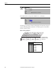
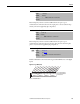
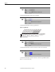
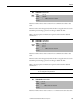
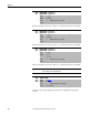
Table Of Contents
- Front Cover
- Important User Information
- Summary of Changes
- Table of Contents
- Introduction
- About the Drive
- Identifying the Drive by Cabinet Assembly ID Number
- LiquiFlo 2.0 Drive Component Locations
- Identifying the Power Module by Model Number
- AC Line I/O Board Description (Frame 3 Only)
- Standard I/O Board Description (Frame 3 Only)
- Combined I/O Board Description (Frame 4 Only)
- DPI Communication Ports
- Optional Equipment
- Planning the Installation
- Mounting The Power Module and Grounding the Drive
- Installing Input and Output Power Wiring
- Completing the Installation
- Using the Start-up Routines
- Programming Basics
- Parameter Descriptions
- Troubleshooting the Drive
- Verify that the DC Bus Capacitors are Discharged Before Servicing the Drive
- Determining Drive Status Using the Status LEDs
- About Alarms
- About Faults
- Diagnostic Parameters
- Common Symptoms and Corrective Actions
- Replacement Parts
- Board Replacement, Firmware Setup Procedures
- Troubleshooting the Drive Using the OIM
- Checking the Power Modules with Input Power Off
- Technical Specifications
- Using the OIM
- Installing and Removing the OIM
- Display Description
- OIM Menu Structure
- Powering Up and Adjusting the OIM
- Selecting a Device in the System
- Using the OIM to Program the Drive
- Monitoring the Drive Using the Process Display Screen on the OIM
- Displaying and Changing the OIM Reference
- Customizing the Process Display Screen
- Customizing the Function Keys
- Controlling the Drive From the OIM
- LiquiFlo 2.0 Drive Frame 3 Wiring Diagrams
- LiquiFlo 2.0 Drive Frame 4 Wiring Diagrams
- Index
- Back Cover

140 Rockwell Automation Publication D2-3518-3 - May 2013
Chapter 9
Parameter number whose value is written to a communications device data table.
Parameter number whose value is written to a communications device data table.
Parameter number whose value is written to a communications device data table.
Selects the type of input signal being used for user-configurable analog inputs
1 and 2.
312
313
Data Out B1- Link B Word 1
Data Out B2 - Link B Word 2
Range: 0...387 [1]
Default: 0 (Disabled)
Access: 1 Path: Communication > Datalinks
See also:
314
315
Data Out C1- Link C Word 1
Data Out C2 - Link C Word 2
Range: 0...387 [1]
Default: 0 (Disabled)
Access: 1 Path: Communication > Datalinks
See also:
316
317
Data Out D1- Link D Word 1
Data Out D2 - Link D Word 2
Range: 0...387 [1]
Default: 316 = 33
317 = 218
Access: 1 Path: Communication > Datalinks
See also:
IMPORTANT
In Liquiflo 2.0 drives, datalink D is used for inverter/rectifier communication.
Do not change these two parameters.
320 Anlg In Config
Range: See Figure 64
Default: See Figure 64
Access: 0 Path: Inputs & Outputs > Analog Inputs
See also: 322, 323, 325, 326