
Owner's manual
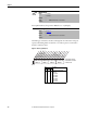
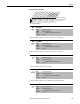
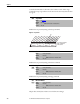
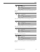
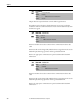
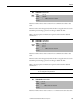
Table Of Contents
- Front Cover
- Important User Information
- Summary of Changes
- Table of Contents
- Introduction
- About the Drive
- Identifying the Drive by Cabinet Assembly ID Number
- LiquiFlo 2.0 Drive Component Locations
- Identifying the Power Module by Model Number
- AC Line I/O Board Description (Frame 3 Only)
- Standard I/O Board Description (Frame 3 Only)
- Combined I/O Board Description (Frame 4 Only)
- DPI Communication Ports
- Optional Equipment
- Planning the Installation
- Mounting The Power Module and Grounding the Drive
- Installing Input and Output Power Wiring
- Completing the Installation
- Using the Start-up Routines
- Programming Basics
- Parameter Descriptions
- Troubleshooting the Drive
- Verify that the DC Bus Capacitors are Discharged Before Servicing the Drive
- Determining Drive Status Using the Status LEDs
- About Alarms
- About Faults
- Diagnostic Parameters
- Common Symptoms and Corrective Actions
- Replacement Parts
- Board Replacement, Firmware Setup Procedures
- Troubleshooting the Drive Using the OIM
- Checking the Power Modules with Input Power Off
- Technical Specifications
- Using the OIM
- Installing and Removing the OIM
- Display Description
- OIM Menu Structure
- Powering Up and Adjusting the OIM
- Selecting a Device in the System
- Using the OIM to Program the Drive
- Monitoring the Drive Using the Process Display Screen on the OIM
- Displaying and Changing the OIM Reference
- Customizing the Process Display Screen
- Customizing the Function Keys
- Controlling the Drive From the OIM
- LiquiFlo 2.0 Drive Frame 3 Wiring Diagrams
- LiquiFlo 2.0 Drive Frame 4 Wiring Diagrams
- Index
- Back Cover
Rockwell Automation Publication D2-3518-3 - May 2013 135
Chapter 9
Figure 62 - Reference Mask (280)
Controls which modules can select Accel Time 1, 2 (140, 141).
Controls which modules can select Decel Time 1, 2. (142, 143)
Controls which modules can clear a fault.
Controls which modules can issue MOP commands to the drive.
281 Accel Mask
Range: See Reference Mask (280)
Default: See Reference Mask (280)
Access: 1 Path: Communication > Masks & Owners
See also: 288...297
282 Decel Mask
Range: See Reference Mask (280)
Default: See Reference Mask (280)
Access: 1 Path: Communication > Masks & Owners
See also: 288...297
283 Fault Clr Mask
Range: See Reference Mask (280)
Default: See Reference Mask (280)
Access: 1 Path: Communication > Masks & Owners
See also: 288...297
284 MOP Mask
Range: See Reference Mask (280)
Default: See Reference Mask (280)
Access: 1 Path: Communication > Masks & Owners
See also: 288...297
285 Local Mask
Range: See Reference Mask (280)
Default: See Reference Mask (280)
Access: 1 Path: Communication > Masks & Owners
See also: 288...297
111111xxxxxxxxxx
0011234567891112131415
1=Control Enabled
0=Control Disabled
x =Reserved
Bit #
Digital In
DPI Port 1
DPI Port 2
DPI Port 3
DPI Port 4
DPI Port 5
Nibble 1Nibble 2Nibble 3Nibble 4
Factory Default Bit Values