
Owner's manual
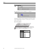
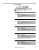
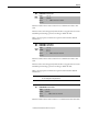
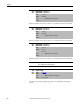
Table Of Contents
- Front Cover
- Important User Information
- Summary of Changes
- Table of Contents
- Introduction
- About the Drive
- Identifying the Drive by Cabinet Assembly ID Number
- LiquiFlo 2.0 Drive Component Locations
- Identifying the Power Module by Model Number
- AC Line I/O Board Description (Frame 3 Only)
- Standard I/O Board Description (Frame 3 Only)
- Combined I/O Board Description (Frame 4 Only)
- DPI Communication Ports
- Optional Equipment
- Planning the Installation
- Mounting The Power Module and Grounding the Drive
- Installing Input and Output Power Wiring
- Completing the Installation
- Using the Start-up Routines
- Programming Basics
- Parameter Descriptions
- Troubleshooting the Drive
- Verify that the DC Bus Capacitors are Discharged Before Servicing the Drive
- Determining Drive Status Using the Status LEDs
- About Alarms
- About Faults
- Diagnostic Parameters
- Common Symptoms and Corrective Actions
- Replacement Parts
- Board Replacement, Firmware Setup Procedures
- Troubleshooting the Drive Using the OIM
- Checking the Power Modules with Input Power Off
- Technical Specifications
- Using the OIM
- Installing and Removing the OIM
- Display Description
- OIM Menu Structure
- Powering Up and Adjusting the OIM
- Selecting a Device in the System
- Using the OIM to Program the Drive
- Monitoring the Drive Using the Process Display Screen on the OIM
- Displaying and Changing the OIM Reference
- Customizing the Process Display Screen
- Customizing the Function Keys
- Controlling the Drive From the OIM
- LiquiFlo 2.0 Drive Frame 3 Wiring Diagrams
- LiquiFlo 2.0 Drive Frame 4 Wiring Diagrams
- Index
- Back Cover
Rockwell Automation Publication D2-3518-3 - May 2013 131
Chapter 9
Selects alarm conditions that initiate a drive alarm. See Chapter 10
for more
information about alarms.
Figure 58 - Alarm Config 1 (259)
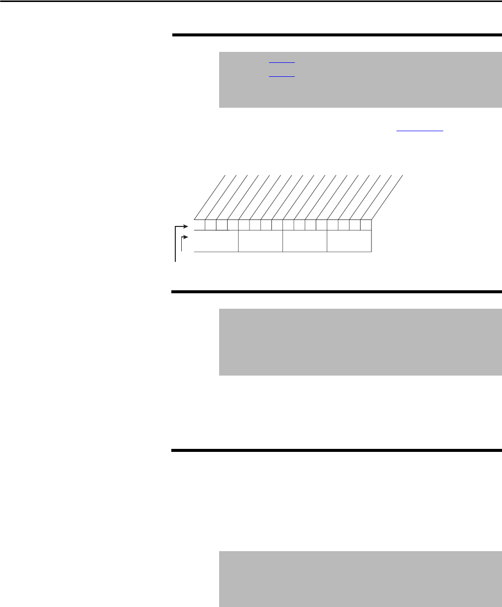
Resets all Alarm1...8 Code parameters (262...269) to zero.
After a Clear Alarm Queue operation, the value of this parameter returns to 0 for
Ready.
A code that represents a drive alarm. The codes appear in the order that the
alarms occur. The first code in is the first out. A time stamp is not available with
alarms.
259 Alarm Config 1
Range: See Figure 58
Default: See Figure 58
Access: 1 Path: Utility > Alarms
See also:
261 Alarm Clear
Range: 0 = Ready
1 = Clr Alarm Que
Default: 0 = Ready
Access: 1 Path: Utility > Alarms
See also: 262...269
262
263
264
265
266
267
268
269
Alarm 1 Code
Alarm 2 Code
Alarm 3 Code
Alarm 4 Code
Alarm 5 Code
Alarm 6 Code
Alarm 7 Code
Alarm 8 Code
Range: 0...65535
Default: Read Only
Access: 1 Path: Utility > Alarms
See also: 261
1
111
1
1
1
1
111
11
=Enabled
0=Disabled
x=Reserved
Bit #
Factory Default Bit Values
xxxx
0011234567891112131415
Prechrg Actv
UnderVoltage
Power Loss
Str At PwrUp
Anlg in Loss
IntDBRes OH
Drv OL Lvl 1
Drv OL LVl 2
Decel Inhibit
Waking
Not Synced
Phased ACB
Nibble 1Nibble 2Nibble 3Nibble 4