
Owner's manual
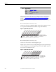
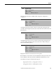
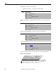
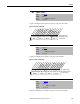
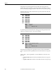
Table Of Contents
- Front Cover
- Important User Information
- Summary of Changes
- Table of Contents
- Introduction
- About the Drive
- Identifying the Drive by Cabinet Assembly ID Number
- LiquiFlo 2.0 Drive Component Locations
- Identifying the Power Module by Model Number
- AC Line I/O Board Description (Frame 3 Only)
- Standard I/O Board Description (Frame 3 Only)
- Combined I/O Board Description (Frame 4 Only)
- DPI Communication Ports
- Optional Equipment
- Planning the Installation
- Mounting The Power Module and Grounding the Drive
- Installing Input and Output Power Wiring
- Completing the Installation
- Using the Start-up Routines
- Programming Basics
- Parameter Descriptions
- Troubleshooting the Drive
- Verify that the DC Bus Capacitors are Discharged Before Servicing the Drive
- Determining Drive Status Using the Status LEDs
- About Alarms
- About Faults
- Diagnostic Parameters
- Common Symptoms and Corrective Actions
- Replacement Parts
- Board Replacement, Firmware Setup Procedures
- Troubleshooting the Drive Using the OIM
- Checking the Power Modules with Input Power Off
- Technical Specifications
- Using the OIM
- Installing and Removing the OIM
- Display Description
- OIM Menu Structure
- Powering Up and Adjusting the OIM
- Selecting a Device in the System
- Using the OIM to Program the Drive
- Monitoring the Drive Using the Process Display Screen on the OIM
- Displaying and Changing the OIM Reference
- Customizing the Process Display Screen
- Customizing the Function Keys
- Controlling the Drive From the OIM
- LiquiFlo 2.0 Drive Frame 3 Wiring Diagrams
- LiquiFlo 2.0 Drive Frame 4 Wiring Diagrams
- Index
- Back Cover
130 Rockwell Automation Publication D2-3518-3 - May 2013
Chapter 9
This parameter is used along with the inverter fault timestamp parameters
(Fault n Time parameters below) to determine whether a drive/inverter fault in
the inverter fault queue happened before or after the most recent drive powerup.
This value rolls over to 0 after the drive has been powered on for more than the
maximum value shown.
A code that represents a drive fault. The codes appear in these parameters in the
order they occur. Fault 1 Code = the most recent fault.
The time between initial power up and the occurrence of the associated fault.
Can be compared to Power Up Marker for the time from the most recent power
up.
(Fault n Time) – (Power Up Marker) = the time difference to the most recent
power up:
• A negative value indicates a fault occurred before the most recent power
up.
• A positive value indicates a fault occurred after the most recent power up.
243
245
247
249
251
253
255
257
Fault 1 Code
Fault 2 Code
Fault 3 Code
Fault 4 Code
Fault 5 Code
Fault 6 Code
Fault 7 Code
Fault 8 Code
Range: 0000...65535
Default: Read Only
Access: 1 Path: Utility > Faults
See also:
244
246
248
250
252
254
256
258
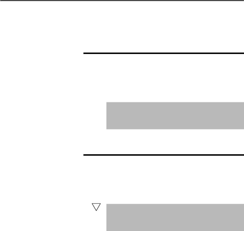
Fault 1 Time
Fault 2 Time
Fault 3 Time
Fault 4 Time
Fault 5 Time
Fault 6 Time
Fault 7 Time
Fault 8 Time
Range: 0.0000...429,496.7295 [0.0001 Hr]
Default: Read Only
Access: 1 Path: Utility > Faults
See also: 242
32