
Owner's manual

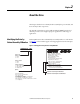
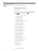
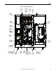
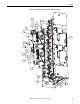
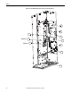
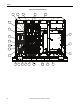
Table Of Contents
- Front Cover
- Important User Information
- Summary of Changes
- Table of Contents
- Introduction
- About the Drive
- Identifying the Drive by Cabinet Assembly ID Number
- LiquiFlo 2.0 Drive Component Locations
- Identifying the Power Module by Model Number
- AC Line I/O Board Description (Frame 3 Only)
- Standard I/O Board Description (Frame 3 Only)
- Combined I/O Board Description (Frame 4 Only)
- DPI Communication Ports
- Optional Equipment
- Planning the Installation
- Mounting The Power Module and Grounding the Drive
- Installing Input and Output Power Wiring
- Completing the Installation
- Using the Start-up Routines
- Programming Basics
- Parameter Descriptions
- Troubleshooting the Drive
- Verify that the DC Bus Capacitors are Discharged Before Servicing the Drive
- Determining Drive Status Using the Status LEDs
- About Alarms
- About Faults
- Diagnostic Parameters
- Common Symptoms and Corrective Actions
- Replacement Parts
- Board Replacement, Firmware Setup Procedures
- Troubleshooting the Drive Using the OIM
- Checking the Power Modules with Input Power Off
- Technical Specifications
- Using the OIM
- Installing and Removing the OIM
- Display Description
- OIM Menu Structure
- Powering Up and Adjusting the OIM
- Selecting a Device in the System
- Using the OIM to Program the Drive
- Monitoring the Drive Using the Process Display Screen on the OIM
- Displaying and Changing the OIM Reference
- Customizing the Process Display Screen
- Customizing the Function Keys
- Controlling the Drive From the OIM
- LiquiFlo 2.0 Drive Frame 3 Wiring Diagrams
- LiquiFlo 2.0 Drive Frame 4 Wiring Diagrams
- Index
- Back Cover
Rockwell Automation Publication D2-3518-3 - May 2013 13
Chapter 2
About the Drive
This chapter describes how to identify the drive assembly, the power module, and
shows the major drive components.
The LiquiFlo 2.0 AC drive is a pulse-width-modulated (PWM) liquid-cooled
drive that provides vector and general purpose regulation for a wide range of
applications.
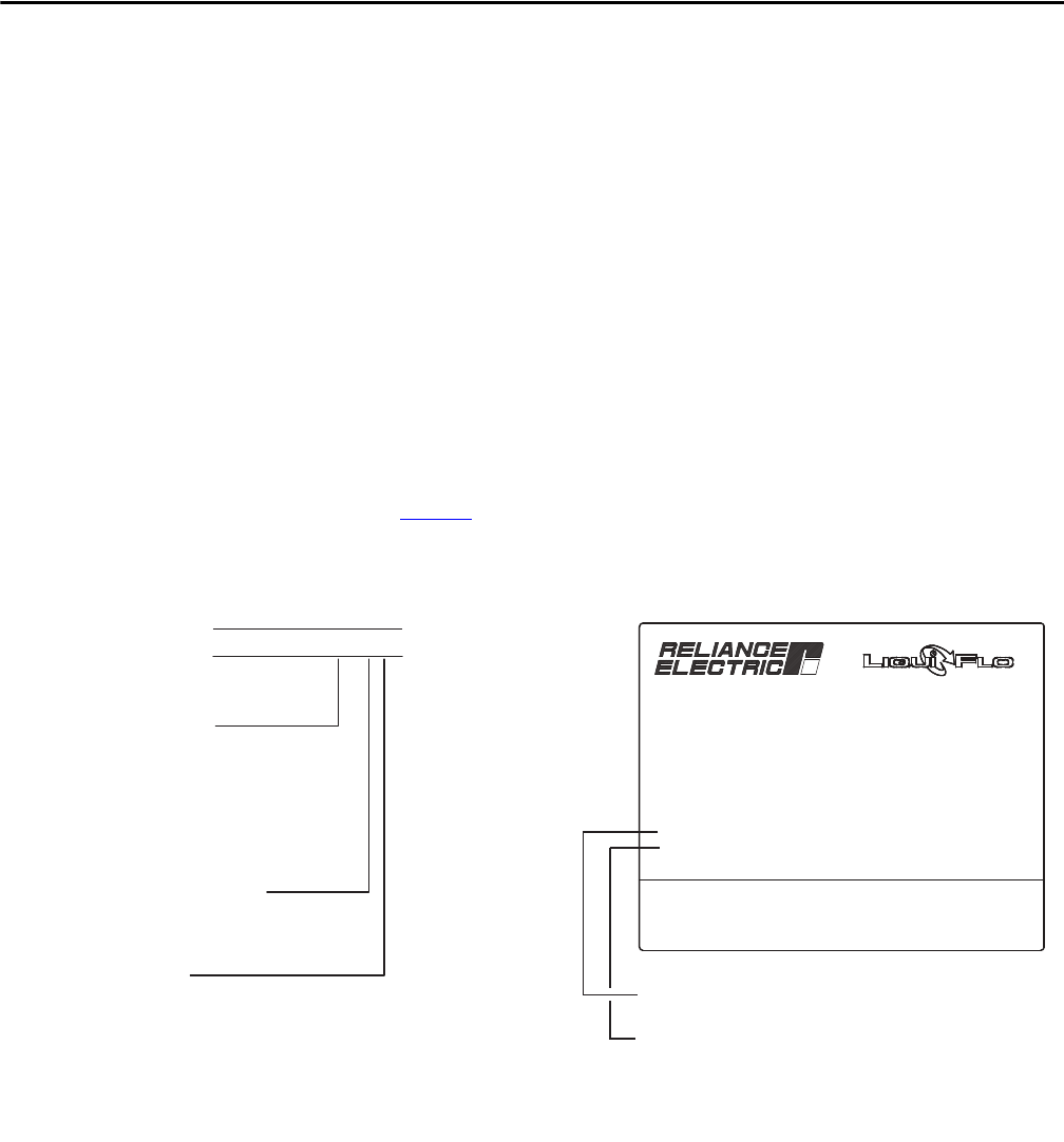
Identifying the Drive by
Cabinet Assembly ID Number
Each LiquiFlo 2.0 AC drive is identified by its assembly number or order number
(see Figure 1
). These numbers appear on the shipping label and on the nameplate
of the drive.
Figure 1 - Identifying the Drive by Cabinet Assembly ID Number
Made in USA by Rockwell Automation
Input: 440-480VAC 60HZ 3PH
Output: 480VAC 405A 0-250 Hz
Type Enclosure: TYPE 1
Short Circuit Rating: 65kAIC
ID NO. Cab. Assy: 180264-A03-600
Cabinet Assy S/N: XXXXXXXXXX
PWR Mod. S/N: XXXXXXXXXXX
PWR Mod. M/N: LF200460AAR
Mfg On: XX-XX-XX
Design Pressure: 185 psig
Coolant Type: R134a OR Treated Water
Max. Ambient: 40˚C
Frame Code
Frame 3 180264
3 = 2AA
6 = 2CC
Frame 4 180580
7 = 4AA
9 = 4CC
Voltage (3-PH input)
3 = 380 - 415V, 50 Hz
6 = 440 - 480V, 60 Hz
8 = 346V, 50 Hz
Options
180264-A 03 - 3 00
180580-A 09 - 6 AA
Cabinet Assembly ID Number
Cabinet Assembly Serial Number
AA = 3PH Meter Kit
BA = 100 kAIC Circuit Breaker
CA = CE Touch Kit
KA = Meter Kit + 100 kAIC Circuit Breaker
LA = Meter Kit + CE Kit
TA = 100 kAIC Circuit Breaker + CE Kit
ZB = Meter Kit + 100 kAIC Circuit Breaker + CE Kit
00 = No Options