
Owner's manual
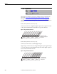
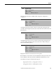
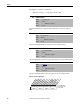
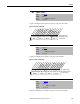
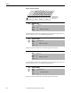
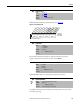
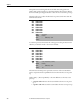
Table Of Contents
- Front Cover
- Important User Information
- Summary of Changes
- Table of Contents
- Introduction
- About the Drive
- Identifying the Drive by Cabinet Assembly ID Number
- LiquiFlo 2.0 Drive Component Locations
- Identifying the Power Module by Model Number
- AC Line I/O Board Description (Frame 3 Only)
- Standard I/O Board Description (Frame 3 Only)
- Combined I/O Board Description (Frame 4 Only)
- DPI Communication Ports
- Optional Equipment
- Planning the Installation
- Mounting The Power Module and Grounding the Drive
- Installing Input and Output Power Wiring
- Completing the Installation
- Using the Start-up Routines
- Programming Basics
- Parameter Descriptions
- Troubleshooting the Drive
- Verify that the DC Bus Capacitors are Discharged Before Servicing the Drive
- Determining Drive Status Using the Status LEDs
- About Alarms
- About Faults
- Diagnostic Parameters
- Common Symptoms and Corrective Actions
- Replacement Parts
- Board Replacement, Firmware Setup Procedures
- Troubleshooting the Drive Using the OIM
- Checking the Power Modules with Input Power Off
- Technical Specifications
- Using the OIM
- Installing and Removing the OIM
- Display Description
- OIM Menu Structure
- Powering Up and Adjusting the OIM
- Selecting a Device in the System
- Using the OIM to Program the Drive
- Monitoring the Drive Using the Process Display Screen on the OIM
- Displaying and Changing the OIM Reference
- Customizing the Process Display Screen
- Customizing the Function Keys
- Controlling the Drive From the OIM
- LiquiFlo 2.0 Drive Frame 3 Wiring Diagrams
- LiquiFlo 2.0 Drive Frame 4 Wiring Diagrams
- Index
- Back Cover
Rockwell Automation Publication D2-3518-3 - May 2013 129
Chapter 9
Enables/disables annunciation of the faults shown in Figure 57.
Figure 57 - Fault Config 1 (238)
Resets a fault and clears the fault queue. After the fault clear operation is
complete, this parameter returns to the value of 0 for Ready.
Enables/disables a fault reset (clear faults) attempt from any source.
Accumulated hours that inverter had been powered up at the time of the most
recent drive powerup.
238 Fault Config 1
Range: See Figure 57
Default: See Figure 57
Access: 0 Path: Utility > Faults
See also:
240 Fault Clear
Range: 0 = Ready
1 = Clear Faults
2 = Clr Flt Que
Default: 0 = Ready
Access: 1 Path: Utility > Faults
See also:
241 Fault Clear Mode
Range: 0 = Disabled
1 = Enabled
Default: 1 = Enabled
Access: 1 Path: Utility > Faults
See also:
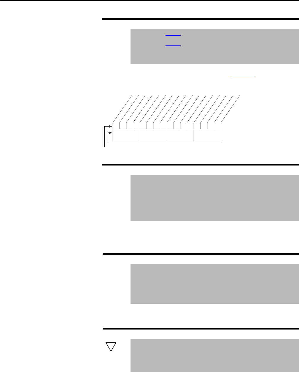
242 Power Up Marker
Range: 0.0000...4,294,967.2925 Hr [0.0001 Hr]
Default: Read Only
Access: 1 Path: Utility > Faults
See also: 244, 246, 248, 250, 252, 254, 256, 258
1x11000xxxxxxxxx
0011234567891112131415
1=Enabled
0=Disabled
x =Reserved
Bit #
Factory Default Bit Values
Power Loss
UnderVoltage
Motor OverLd
Shear Pin
AutRst Tries
Decel Inhibit
Nibble 1Nibble 2Nibble 3Nibble 4
32