
Owner's manual
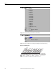
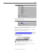
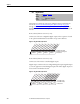
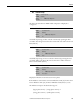
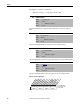
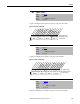
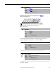
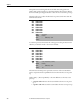
Table Of Contents
- Front Cover
- Important User Information
- Summary of Changes
- Table of Contents
- Introduction
- About the Drive
- Identifying the Drive by Cabinet Assembly ID Number
- LiquiFlo 2.0 Drive Component Locations
- Identifying the Power Module by Model Number
- AC Line I/O Board Description (Frame 3 Only)
- Standard I/O Board Description (Frame 3 Only)
- Combined I/O Board Description (Frame 4 Only)
- DPI Communication Ports
- Optional Equipment
- Planning the Installation
- Mounting The Power Module and Grounding the Drive
- Installing Input and Output Power Wiring
- Completing the Installation
- Using the Start-up Routines
- Programming Basics
- Parameter Descriptions
- Troubleshooting the Drive
- Verify that the DC Bus Capacitors are Discharged Before Servicing the Drive
- Determining Drive Status Using the Status LEDs
- About Alarms
- About Faults
- Diagnostic Parameters
- Common Symptoms and Corrective Actions
- Replacement Parts
- Board Replacement, Firmware Setup Procedures
- Troubleshooting the Drive Using the OIM
- Checking the Power Modules with Input Power Off
- Technical Specifications
- Using the OIM
- Installing and Removing the OIM
- Display Description
- OIM Menu Structure
- Powering Up and Adjusting the OIM
- Selecting a Device in the System
- Using the OIM to Program the Drive
- Monitoring the Drive Using the Process Display Screen on the OIM
- Displaying and Changing the OIM Reference
- Customizing the Process Display Screen
- Customizing the Function Keys
- Controlling the Drive From the OIM
- LiquiFlo 2.0 Drive Frame 3 Wiring Diagrams
- LiquiFlo 2.0 Drive Frame 4 Wiring Diagrams
- Index
- Back Cover
Rockwell Automation Publication D2-3518-3 - May 2013 127
Chapter 9
Captures and displays Drive Status 2 bit pattern at the time of last fault.
Figure 54 - Status 2 @ Fault (228)
Captures and displays Drive Alarm 1 at the time of the last fault.
Figure 55 - Alarm 1 @ Fault (229)
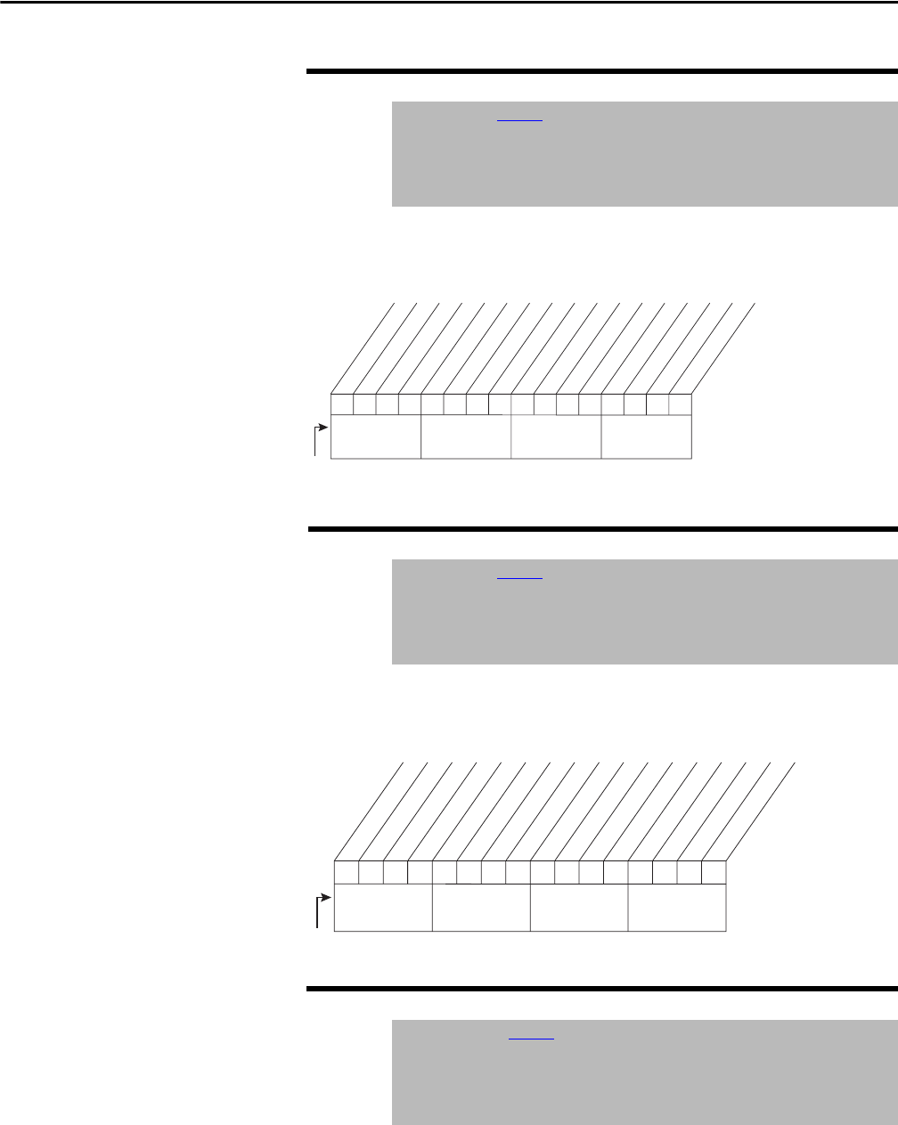
Captures and displays Drive Alarm 2 bit pattern at the time of last fault.
228 Status 2 @ Fault
Range: See Figure 54
Default: Read Only
Access: 1 Path: Utility > Diagnostics
See also: 210, 224...230
229 Alarm 1 @ Fault
Range: See Figure 55
Default: Read Only
Access: 1 Path: Utility > Diagnostics
See also: 211, 224...230
230 Alarm 2 @ Fault
Range: See Figure 56
Default: Read Only
Access: 1 Path: Utility > Diagnostics
See also: 211, 221...230
0000000x000000xx
0011234567891112131415
1=Condition True
0=Condition False
x =Reserved
Bit #
Ready
Active
Running
Jogging
Stopping
DC Braking
AutoTuning
AutoRst Ctdn
AutoRst Act
Curr Limit
Bus Freq Reg
Motor Overld
DPI at 500 k
Nibble 1Nibble 2Nibble 3Nibble 4
000000x000
000
xxx
0011234567891112131415
1=Alarm Active
0=Alarm Inactive
x =Reserved
Bit #
Prechrg Actv
UnderVoltage
Power Loss
Str At PwrUp
Anlg in Loss
IntDBRes OH
Drv OL Lvl 1
Drv OL LVl 2
Decel Inhibit
Waking
Not Synced
Phased ACB
Nibble 1Nibble 2Nibble 3Nibble 4