
Owner's manual
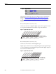
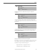
Table Of Contents
- Front Cover
- Important User Information
- Summary of Changes
- Table of Contents
- Introduction
- About the Drive
- Identifying the Drive by Cabinet Assembly ID Number
- LiquiFlo 2.0 Drive Component Locations
- Identifying the Power Module by Model Number
- AC Line I/O Board Description (Frame 3 Only)
- Standard I/O Board Description (Frame 3 Only)
- Combined I/O Board Description (Frame 4 Only)
- DPI Communication Ports
- Optional Equipment
- Planning the Installation
- Mounting The Power Module and Grounding the Drive
- Installing Input and Output Power Wiring
- Completing the Installation
- Using the Start-up Routines
- Programming Basics
- Parameter Descriptions
- Troubleshooting the Drive
- Verify that the DC Bus Capacitors are Discharged Before Servicing the Drive
- Determining Drive Status Using the Status LEDs
- About Alarms
- About Faults
- Diagnostic Parameters
- Common Symptoms and Corrective Actions
- Replacement Parts
- Board Replacement, Firmware Setup Procedures
- Troubleshooting the Drive Using the OIM
- Checking the Power Modules with Input Power Off
- Technical Specifications
- Using the OIM
- Installing and Removing the OIM
- Display Description
- OIM Menu Structure
- Powering Up and Adjusting the OIM
- Selecting a Device in the System
- Using the OIM to Program the Drive
- Monitoring the Drive Using the Process Display Screen on the OIM
- Displaying and Changing the OIM Reference
- Customizing the Process Display Screen
- Customizing the Function Keys
- Controlling the Drive From the OIM
- LiquiFlo 2.0 Drive Frame 3 Wiring Diagrams
- LiquiFlo 2.0 Drive Frame 4 Wiring Diagrams
- Index
- Back Cover
126 Rockwell Automation Publication D2-3518-3 - May 2013
Chapter 9
The imbalance in percent is calculated as:
(Imbalance in amps) ÷ (average phase current) x100.
Captures and displays the output frequency of the drive at the time of the last
fault.
Captures and displays RMS motor amps at the time of the last fault.
Captures and displays the DC bus voltage of the drive at the time of the last fault.
Captures and displays Drive Status 1 bit pattern at the time of the last fault.
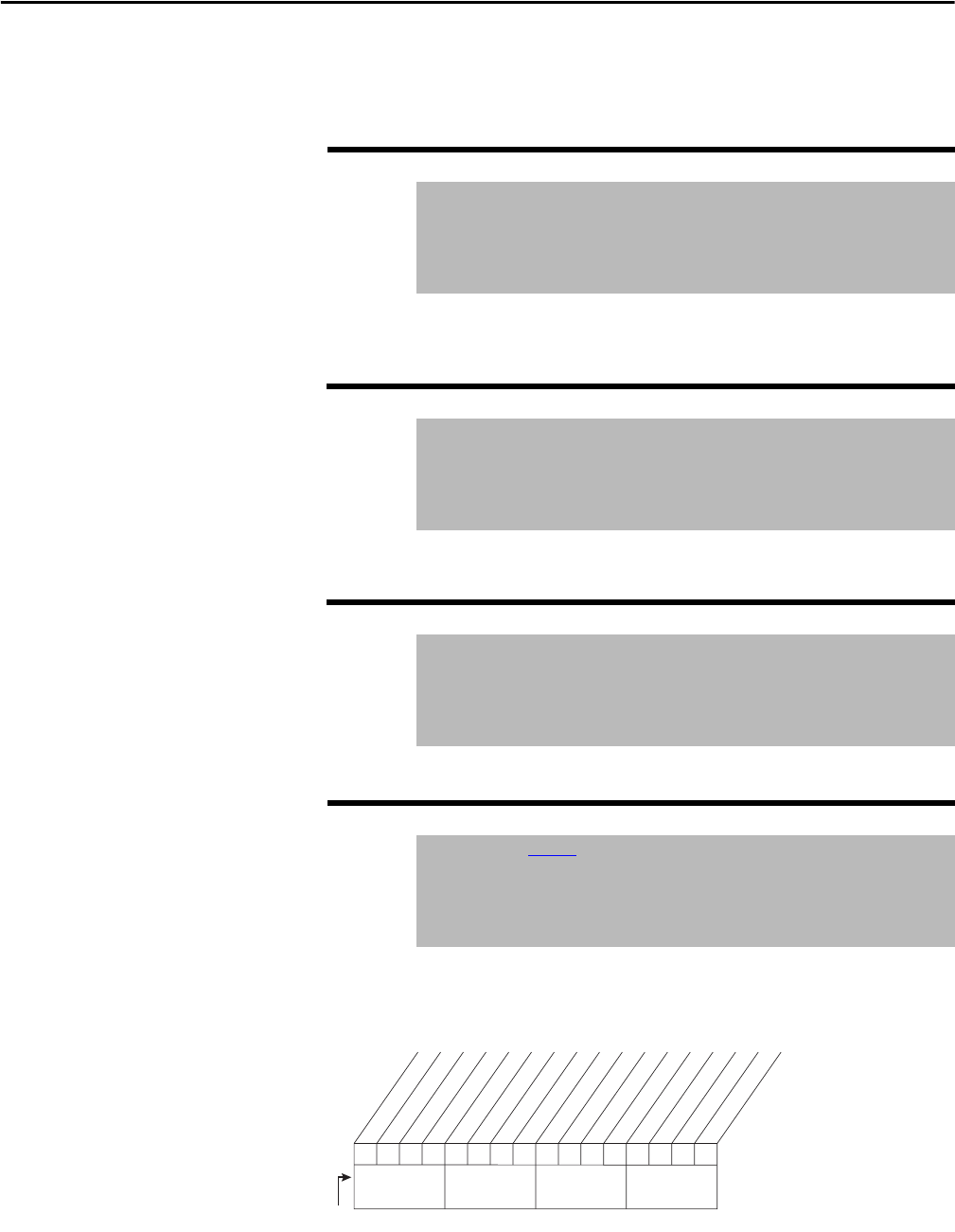
Figure 53 - Status 1 @ Fault (227)
224 Fault Frequency
Range: +/-400.0 Hz [0.1 Hz]
Default: Read Only
Access: 1 Path: Utility > Diagnostics
See also: 225...230
225 Fault Amps
Range: 0.0...3276.7 A [0.1 A]
Default: Read Only
Access: 1 Path: Utility > Diagnostics
See also: 224...230
226 Fault Bus Volts
Range: 0.0...3276.7V DC [0.1V DC]
Default: Read Only
Access: 1 Path: Utility > Diagnostics
See also: 224...230
227 Status 1 @ Fault
Range: See Figure 53
Default: Read Only
Access: 1 Path: Utility > Diagnostics
See also: 209, 224...230
0
0
0
0
000000000000
0011234567891112131415
1=Condition True
0=Condition False
x =Reserved
Bit #
Ready
Active
Command Dir
Actual Dir
Accelerating
Decelerating
Alarm
Faulted
At Speed
Local ID 0
Local ID 1
Local ID 2
Spd Ref ID 0
Spd Ref ID 1
Spd Ref ID 2
Spd Ref ID 3
Nibble 1Nibble 2Nibble 3Nibble 4