
Owner's manual
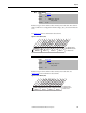
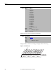
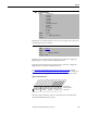
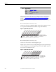
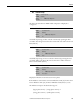
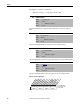
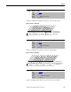
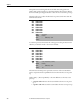
Table Of Contents
- Front Cover
- Important User Information
- Summary of Changes
- Table of Contents
- Introduction
- About the Drive
- Identifying the Drive by Cabinet Assembly ID Number
- LiquiFlo 2.0 Drive Component Locations
- Identifying the Power Module by Model Number
- AC Line I/O Board Description (Frame 3 Only)
- Standard I/O Board Description (Frame 3 Only)
- Combined I/O Board Description (Frame 4 Only)
- DPI Communication Ports
- Optional Equipment
- Planning the Installation
- Mounting The Power Module and Grounding the Drive
- Installing Input and Output Power Wiring
- Completing the Installation
- Using the Start-up Routines
- Programming Basics
- Parameter Descriptions
- Troubleshooting the Drive
- Verify that the DC Bus Capacitors are Discharged Before Servicing the Drive
- Determining Drive Status Using the Status LEDs
- About Alarms
- About Faults
- Diagnostic Parameters
- Common Symptoms and Corrective Actions
- Replacement Parts
- Board Replacement, Firmware Setup Procedures
- Troubleshooting the Drive Using the OIM
- Checking the Power Modules with Input Power Off
- Technical Specifications
- Using the OIM
- Installing and Removing the OIM
- Display Description
- OIM Menu Structure
- Powering Up and Adjusting the OIM
- Selecting a Device in the System
- Using the OIM to Program the Drive
- Monitoring the Drive Using the Process Display Screen on the OIM
- Displaying and Changing the OIM Reference
- Customizing the Process Display Screen
- Customizing the Function Keys
- Controlling the Drive From the OIM
- LiquiFlo 2.0 Drive Frame 3 Wiring Diagrams
- LiquiFlo 2.0 Drive Frame 4 Wiring Diagrams
- Index
- Back Cover

Rockwell Automation Publication D2-3518-3 - May 2013 123
Chapter 9
Displays the source that initiated the most recent stop sequence. It is cleared (set
to 0) during the next start sequence.
For Frame 3 drives, this parameter provides the state of the user-configurable
Digital Inputs on the optional A22 Standard I/O board.
For Frame 4 drives, this parameter provides the state of the user-configurable
Digital Inputs on the A12 Combined I/O board.
See AC Line I/O Board Description (Frame 3 Only)
on page 25 through
Combined I/O Board Description (Frame 4 Only)
on page 29 for a description
of I/O hardware that is present on this drive and is controlled by the inverter.
Figure 50 - Dig In Status (216)
For Frame 3 drives (firmware version 1.x), this parameter is only usable if an
optional Standard I/O board is present.
215 Last Stop Source
Range: 0 = Pwr Removed
1 = DPI Port 1
2 = DPI Port 2
3 = DPI Port 3
4 = DPI Port 4
5 = DPI Port 5
6 = DPI Port 6 (Frame 4 only)
7 = Digital In
8 = Fault
9 = Not Enabled
10 = Sleep
11 = Jog
Default: Read Only
Access: 1 Path: Utility > Diagnostics
See also:
216 Dig In Status
Range: See Figure 50
Default: Read Only
Access: 0 Path: Utility > Diagnostics
See also: 361...366
000000xxxxxxxxxx
0011234567891112131415
1=Input Active
0=Input Not Active
x =Reserved
Bit #
Digital In1
Digital In2
Digital In3
Digital In4
Digital In5
Digital In6
Nibble 1Nibble 2Nibble 3Nibble 4