
Owner's manual
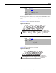
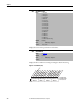
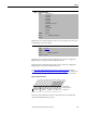
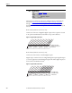
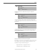
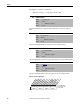
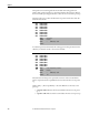
Table Of Contents
- Front Cover
- Important User Information
- Summary of Changes
- Table of Contents
- Introduction
- About the Drive
- Identifying the Drive by Cabinet Assembly ID Number
- LiquiFlo 2.0 Drive Component Locations
- Identifying the Power Module by Model Number
- AC Line I/O Board Description (Frame 3 Only)
- Standard I/O Board Description (Frame 3 Only)
- Combined I/O Board Description (Frame 4 Only)
- DPI Communication Ports
- Optional Equipment
- Planning the Installation
- Mounting The Power Module and Grounding the Drive
- Installing Input and Output Power Wiring
- Completing the Installation
- Using the Start-up Routines
- Programming Basics
- Parameter Descriptions
- Troubleshooting the Drive
- Verify that the DC Bus Capacitors are Discharged Before Servicing the Drive
- Determining Drive Status Using the Status LEDs
- About Alarms
- About Faults
- Diagnostic Parameters
- Common Symptoms and Corrective Actions
- Replacement Parts
- Board Replacement, Firmware Setup Procedures
- Troubleshooting the Drive Using the OIM
- Checking the Power Modules with Input Power Off
- Technical Specifications
- Using the OIM
- Installing and Removing the OIM
- Display Description
- OIM Menu Structure
- Powering Up and Adjusting the OIM
- Selecting a Device in the System
- Using the OIM to Program the Drive
- Monitoring the Drive Using the Process Display Screen on the OIM
- Displaying and Changing the OIM Reference
- Customizing the Process Display Screen
- Customizing the Function Keys
- Controlling the Drive From the OIM
- LiquiFlo 2.0 Drive Frame 3 Wiring Diagrams
- LiquiFlo 2.0 Drive Frame 4 Wiring Diagrams
- Index
- Back Cover

122 Rockwell Automation Publication D2-3518-3 - May 2013
Chapter 9
Displays the source of the speed reference of the drive.
Displays the drive conditions currently preventing the drive from starting.
Figure 49 - Start Inhibits (214)
213 Speed Ref Source
Range: 0 = PI Output
1 = Analog In 1
2 = Analog In 2
3...8 = Reserved
9 = MOP Level
10 = Jog Speed
11 = Preset Spd 1
12 = Preset Spd 2
13 = Preset Spd 3
14 = Preset Spd 4
15 = Preset Spd 5
16 = Preset Spd 6
17 = Preset Spd 7
18 = DPI Port 1
19 = DPI Port 2
20 = DPI Port 3
21 = DPI Port 4
22 = DPI Port 5
23 = DPI Port 6 (Frame 4 only)
Default: Read Only
Access: 1 Path: Utility > Diagnostics
See also: 90, 93, 96, 101
214 Start Inhibits
Range: See Figure 49
Default: Read Only
Access: 0 Path: Utility > Diagnostics
See also:
0000000x0000000x
0011234567891112131415
1=Inhibit True
0=Inhibit False
x =Reserved
Bit #
Fault
Type 2 Alarm
Enable
Rctfr NotRdy
DPI Stop
Params Reset
StartUp Actv
Digital In
DPI Port 1
DPI Port 2
DPI Port 3
DPI Port 4
DPI Port 5
DPI Port 6 (Frame 4)
Nibble 1Nibble 2Nibble 3Nibble 4