
Owner's manual
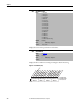
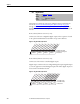
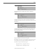
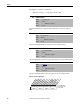
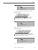
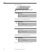
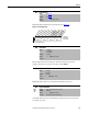
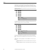
Table Of Contents
- Front Cover
- Important User Information
- Summary of Changes
- Table of Contents
- Introduction
- About the Drive
- Identifying the Drive by Cabinet Assembly ID Number
- LiquiFlo 2.0 Drive Component Locations
- Identifying the Power Module by Model Number
- AC Line I/O Board Description (Frame 3 Only)
- Standard I/O Board Description (Frame 3 Only)
- Combined I/O Board Description (Frame 4 Only)
- DPI Communication Ports
- Optional Equipment
- Planning the Installation
- Mounting The Power Module and Grounding the Drive
- Installing Input and Output Power Wiring
- Completing the Installation
- Using the Start-up Routines
- Programming Basics
- Parameter Descriptions
- Troubleshooting the Drive
- Verify that the DC Bus Capacitors are Discharged Before Servicing the Drive
- Determining Drive Status Using the Status LEDs
- About Alarms
- About Faults
- Diagnostic Parameters
- Common Symptoms and Corrective Actions
- Replacement Parts
- Board Replacement, Firmware Setup Procedures
- Troubleshooting the Drive Using the OIM
- Checking the Power Modules with Input Power Off
- Technical Specifications
- Using the OIM
- Installing and Removing the OIM
- Display Description
- OIM Menu Structure
- Powering Up and Adjusting the OIM
- Selecting a Device in the System
- Using the OIM to Program the Drive
- Monitoring the Drive Using the Process Display Screen on the OIM
- Displaying and Changing the OIM Reference
- Customizing the Process Display Screen
- Customizing the Function Keys
- Controlling the Drive From the OIM
- LiquiFlo 2.0 Drive Frame 3 Wiring Diagrams
- LiquiFlo 2.0 Drive Frame 4 Wiring Diagrams
- Index
- Back Cover

Rockwell Automation Publication D2-3518-3 - May 2013 121
Chapter 9
Indicates Type 1 alarm conditions that currently exist in the drive. Note that for
alarm conditions not configured in Alarm Config 1 (259), the status indicated is
a zero.
See Chapter 10
for more information about alarms.
Figure 47 - Drive Alarm 1 (211)
Indicates Type 2 alarm conditions that currently exist in the drive. See
Chapter 10
for more information about alarms.
Figure 48 - Drive Alarm 2 (212)
211 Drive Alarm 1
Range: See Figure 47
Default: Read Only
Access: 1 Path: Utility > Diagnostics
Utility > Alarms
See also: 212, 259
212 Drive Alarm 2
Range: See Figure 48
Default: Read Only
Access: 1 Path: Utility > Diagnostics
Utility > Alarms
See also: 211
000000x000
000
xxx
0011234567891112131415
1=Alarm Active
0=Alarm Inactive
x =Reserved
Bit #
Prechrg Actv
UnderVoltage
Power Loss
Str At PwrUp
Anlg in Loss
IntDBRes OH
Drv OL Lvl 1
Drv OL LVl 2
Decel Inhibit
Waking
Not Synced
Phased ACB
Nibble 1Nibble 2Nibble 3Nibble 4
0000000000000xxx
0011234567891112131415
1=Alarm Active
0=Alarm Inactive
x =Reserved
Bit #
DigIn CflctA
DigIn CflctB
DigIn CflctC
Bipolr Cflct
MtrTyp Cflct
NP Hz Cflct
MaxFrq Cflct
VHz NegSlope
IR Vlts Rang
FlxAmps Rang
SpdRef Cflct
Ixo Volt Range
Sleep Config
Nibble 1Nibble 2Nibble 3Nibble 4