
Owner's manual
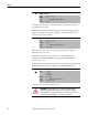
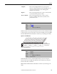
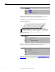
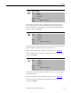
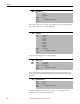
Table Of Contents
- Front Cover
- Important User Information
- Summary of Changes
- Table of Contents
- Introduction
- About the Drive
- Identifying the Drive by Cabinet Assembly ID Number
- LiquiFlo 2.0 Drive Component Locations
- Identifying the Power Module by Model Number
- AC Line I/O Board Description (Frame 3 Only)
- Standard I/O Board Description (Frame 3 Only)
- Combined I/O Board Description (Frame 4 Only)
- DPI Communication Ports
- Optional Equipment
- Planning the Installation
- Mounting The Power Module and Grounding the Drive
- Installing Input and Output Power Wiring
- Completing the Installation
- Using the Start-up Routines
- Programming Basics
- Parameter Descriptions
- Troubleshooting the Drive
- Verify that the DC Bus Capacitors are Discharged Before Servicing the Drive
- Determining Drive Status Using the Status LEDs
- About Alarms
- About Faults
- Diagnostic Parameters
- Common Symptoms and Corrective Actions
- Replacement Parts
- Board Replacement, Firmware Setup Procedures
- Troubleshooting the Drive Using the OIM
- Checking the Power Modules with Input Power Off
- Technical Specifications
- Using the OIM
- Installing and Removing the OIM
- Display Description
- OIM Menu Structure
- Powering Up and Adjusting the OIM
- Selecting a Device in the System
- Using the OIM to Program the Drive
- Monitoring the Drive Using the Process Display Screen on the OIM
- Displaying and Changing the OIM Reference
- Customizing the Process Display Screen
- Customizing the Function Keys
- Controlling the Drive From the OIM
- LiquiFlo 2.0 Drive Frame 3 Wiring Diagrams
- LiquiFlo 2.0 Drive Frame 4 Wiring Diagrams
- Index
- Back Cover
Rockwell Automation Publication D2-3518-3 - May 2013 119
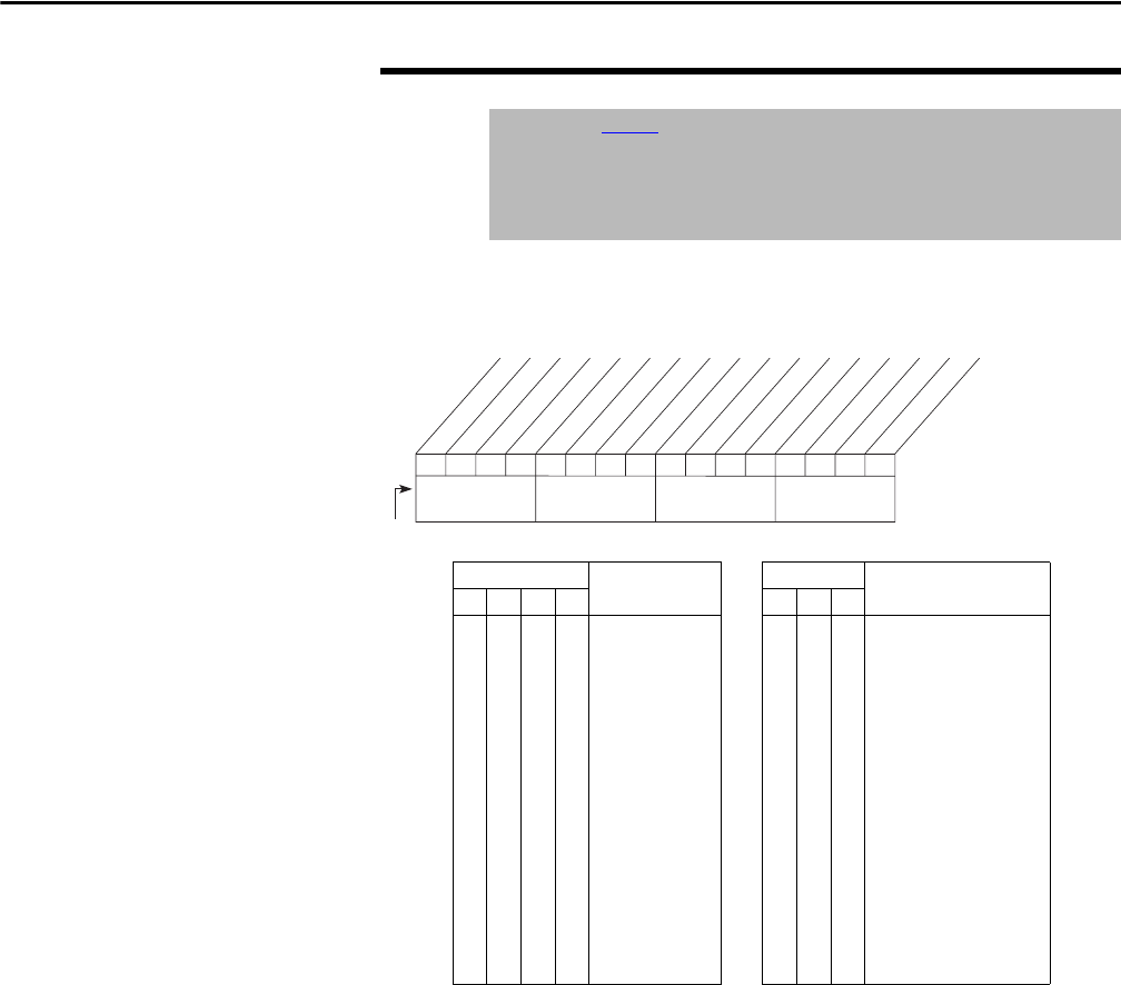
Chapter 9
Present operating condition of the drive.
Figure 45 - Drive Status 1 (209)
209 Drive Status 1
Range: See Figure 45
Default: Read Only
Access: 1 Path: Utility > Diagnostics
See also: 210
Bits
(2)
Description Bits
(1)
Description
15 14 13 12 11 10 9
0
0
0
0
0
0
0
0
1
1
1
1
1
1
1
0
0
0
0
1
1
1
1
0
0
0
0
1
1
1
0
0
1
1
0
0
1
1
0
0
1
1
0
0
1
0
1
0
1
0
1
0
1
0
1
0
1
0
1
0
Ref A Auto
Preset 1 Auto
Preset 2 Auto
Preset 3 Auto
Preset 4 Auto
Preset 5 Auto
Preset 6 Auto
Preset 7 Auto
TB Manual
Port 1 Manual
Port 2 Manual
Port 3 Manual
Port 4 Manual
Port 5 Manual
Port 6 Manual
0
0
0
0
1
1
1
1
0
0
1
1
0
0
1
1
0
1
0
1
0
1
0
1
Port 0 (TB)
Port 1
Port 2
Port 3
Port 4
Port 5
Port 6
No Local Control
0110000101110000
0011234567891112131415
1=Condition True
0=Condition False
x =Reserved
Bit #
Ready
Active
Command Dir
Actual Dir
Accelerating
Decelerating
Alarm
Faulted
At Speed
Local ID 0
(1)
Local ID 1
(1)
Local ID 2
(1)
Spd Ref ID 0
(2)
Spd Ref ID 1
(2)
Spd Ref ID 2
(2)
Spd Ref ID 3
(2)
Nibble 1Nibble 2Nibble 3Nibble 4