
Owner's manual
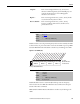
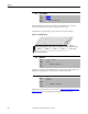
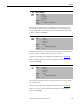
Table Of Contents
- Front Cover
- Important User Information
- Summary of Changes
- Table of Contents
- Introduction
- About the Drive
- Identifying the Drive by Cabinet Assembly ID Number
- LiquiFlo 2.0 Drive Component Locations
- Identifying the Power Module by Model Number
- AC Line I/O Board Description (Frame 3 Only)
- Standard I/O Board Description (Frame 3 Only)
- Combined I/O Board Description (Frame 4 Only)
- DPI Communication Ports
- Optional Equipment
- Planning the Installation
- Mounting The Power Module and Grounding the Drive
- Installing Input and Output Power Wiring
- Completing the Installation
- Using the Start-up Routines
- Programming Basics
- Parameter Descriptions
- Troubleshooting the Drive
- Verify that the DC Bus Capacitors are Discharged Before Servicing the Drive
- Determining Drive Status Using the Status LEDs
- About Alarms
- About Faults
- Diagnostic Parameters
- Common Symptoms and Corrective Actions
- Replacement Parts
- Board Replacement, Firmware Setup Procedures
- Troubleshooting the Drive Using the OIM
- Checking the Power Modules with Input Power Off
- Technical Specifications
- Using the OIM
- Installing and Removing the OIM
- Display Description
- OIM Menu Structure
- Powering Up and Adjusting the OIM
- Selecting a Device in the System
- Using the OIM to Program the Drive
- Monitoring the Drive Using the Process Display Screen on the OIM
- Displaying and Changing the OIM Reference
- Customizing the Process Display Screen
- Customizing the Function Keys
- Controlling the Drive From the OIM
- LiquiFlo 2.0 Drive Frame 3 Wiring Diagrams
- LiquiFlo 2.0 Drive Frame 4 Wiring Diagrams
- Index
- Back Cover

Rockwell Automation Publication D2-3518-3 - May 2013 117
Chapter 9
Resets all inverter parameter values to defaults. Option 1 resets the inverter to
factory settings. Options 2 and 3 resets the inverter to alternate voltage and
current rating. After a restore defaults operation is performed, the value of this
parameter returns to 0 for Ready.
Loads a previously saved set of inverter parameter values from a selected user set
location in drive non-volatile memory to active drive memory.
An F-Key on the OIM can be configured for this function. See Appendix B
.
After a Load From User Set operation is performed, the value of this parameter
returns to 0 for Ready.
Saves the inverter parameter values in active drive memory to a user set in drive
non-volatile memory.
An F-Key on the OIM can be configured for this function. See Appendix B
.
After a Save To User Set operation is performed, the value of this parameter
returns to 0 for Ready.
197 Reset To Defalts
Range: 0 = Ready
1 = Factory
2 = Low Voltage
3 = High Voltage
Default: 0 = Ready
Access: 0 Path: Utility > Drive Memory
See also:
198 Load Frm Usr Set
Range: 0 = Ready
1 = User Set 1
2 = User Set 2
3 = User Set 3
Default: 0 = Ready
Access: 0 Path: Utility > Drive Memory
See also: 199
199 Save To User Set
Range: 0 = Ready
1 = User Set 1
2 = User Set 2
3 = User Set 3
Default: 0 = Ready
Access: 0 Path: Utility > Drive Memory
See also: 198