
Owner's manual
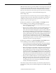
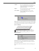
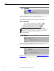
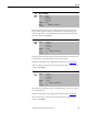
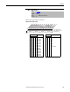
Table Of Contents
- Front Cover
- Important User Information
- Summary of Changes
- Table of Contents
- Introduction
- About the Drive
- Identifying the Drive by Cabinet Assembly ID Number
- LiquiFlo 2.0 Drive Component Locations
- Identifying the Power Module by Model Number
- AC Line I/O Board Description (Frame 3 Only)
- Standard I/O Board Description (Frame 3 Only)
- Combined I/O Board Description (Frame 4 Only)
- DPI Communication Ports
- Optional Equipment
- Planning the Installation
- Mounting The Power Module and Grounding the Drive
- Installing Input and Output Power Wiring
- Completing the Installation
- Using the Start-up Routines
- Programming Basics
- Parameter Descriptions
- Troubleshooting the Drive
- Verify that the DC Bus Capacitors are Discharged Before Servicing the Drive
- Determining Drive Status Using the Status LEDs
- About Alarms
- About Faults
- Diagnostic Parameters
- Common Symptoms and Corrective Actions
- Replacement Parts
- Board Replacement, Firmware Setup Procedures
- Troubleshooting the Drive Using the OIM
- Checking the Power Modules with Input Power Off
- Technical Specifications
- Using the OIM
- Installing and Removing the OIM
- Display Description
- OIM Menu Structure
- Powering Up and Adjusting the OIM
- Selecting a Device in the System
- Using the OIM to Program the Drive
- Monitoring the Drive Using the Process Display Screen on the OIM
- Displaying and Changing the OIM Reference
- Customizing the Process Display Screen
- Customizing the Function Keys
- Controlling the Drive From the OIM
- LiquiFlo 2.0 Drive Frame 3 Wiring Diagrams
- LiquiFlo 2.0 Drive Frame 4 Wiring Diagrams
- Index
- Back Cover

116 Rockwell Automation Publication D2-3518-3 - May 2013
Chapter 9
Enables/disables the feature that saves the present MOP (motor-operated
potentiometer) frequency reference at power down or at stop.
The MOP is an output frequency value internal to the drive firmware.
Figure 44 - Save MOP Ref (194)
Sets the rate of change of the MOP reference in response to a digital input. The
MOP is an output frequency value internal to the drive firmware.
Displays the present parameter access level. See Selecting the Parameter Access
Level on page 63 for more information about parameter access levels.
194 Save MOP Ref
Range: See Figure 44
Default: See Figure 44
Access: 1 Path: Utility > MOP Config
See also:
195 MOP Rate
Range: 0.2...250.0 [0.1 Hz/sec]
Default: 1.0 Hz/sec
Access: 1 Path: Utility > MOP Config
See also:
196 Param Access Lvl
Range: 0 = Basic
1 = Advanced
Default: 0
Access: 0 Path: Utility > Drive Memory
See also:
0xx 0xxxxxxxxxxxx
0011234567891112131415
1=Save
0=Do Not Save
x =Reserved
Bit #
Factory Default Bit Values
At Powr Down
At Stop
Nibble 1Nibble 2Nibble 3Nibble 4