
Owner's manual
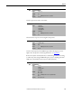
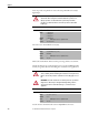
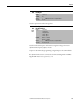
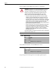
Table Of Contents
- Front Cover
- Important User Information
- Summary of Changes
- Table of Contents
- Introduction
- About the Drive
- Identifying the Drive by Cabinet Assembly ID Number
- LiquiFlo 2.0 Drive Component Locations
- Identifying the Power Module by Model Number
- AC Line I/O Board Description (Frame 3 Only)
- Standard I/O Board Description (Frame 3 Only)
- Combined I/O Board Description (Frame 4 Only)
- DPI Communication Ports
- Optional Equipment
- Planning the Installation
- Mounting The Power Module and Grounding the Drive
- Installing Input and Output Power Wiring
- Completing the Installation
- Using the Start-up Routines
- Programming Basics
- Parameter Descriptions
- Troubleshooting the Drive
- Verify that the DC Bus Capacitors are Discharged Before Servicing the Drive
- Determining Drive Status Using the Status LEDs
- About Alarms
- About Faults
- Diagnostic Parameters
- Common Symptoms and Corrective Actions
- Replacement Parts
- Board Replacement, Firmware Setup Procedures
- Troubleshooting the Drive Using the OIM
- Checking the Power Modules with Input Power Off
- Technical Specifications
- Using the OIM
- Installing and Removing the OIM
- Display Description
- OIM Menu Structure
- Powering Up and Adjusting the OIM
- Selecting a Device in the System
- Using the OIM to Program the Drive
- Monitoring the Drive Using the Process Display Screen on the OIM
- Displaying and Changing the OIM Reference
- Customizing the Process Display Screen
- Customizing the Function Keys
- Controlling the Drive From the OIM
- LiquiFlo 2.0 Drive Frame 3 Wiring Diagrams
- LiquiFlo 2.0 Drive Frame 4 Wiring Diagrams
- Index
- Back Cover

Rockwell Automation Publication D2-3518-3 - May 2013 105
Chapter 9
Sets the responsiveness of the current limit.
Selects the drive’s response to increasing drive temperature.
Sets the carrier frequency for the PWM output. Drive derating may occur at
higher carrier frequencies. For derating information, see Appendix A
.
If the Carrier Sync Lost fault (fault 247) is enabled using rectifier Fault Config
(rectifier 238), then setting the PWM Frequency (151) to anything other than
4 kHz causes an immediate Carrier Sync Lost fault (fault 247).
149 Current Lmt Gain
Range: 0...5000 [1]
Default: 200
Access: 1 Path: Dynamic Control > Load Limits
See also: 147, 148
150 Drive OL Mode
Range: 0 = Disabled
1 = Reduce CLim
2 = Reduce PWM
3 = Both-PWM 1st
Default: 0 = Disabled
Access: 1 Path: Dynamic Control > Load Limits
See also: 219
151 PWM Frequency
Range: 2...4 kHz [1 kHz]
Default: 2 kHz
Access: 1 Path: Dynamic Control > Load Limits
See also: 146, 149
155
156
Stop Mode A
Stop Mode B
Range: 0 = Coast
1 = Ramp
2 = Ramp to Hold
3 = DC Brake
Default: 155: 0 = Coast
156: 0 = Coast
Access: 155 = 0
156 = 0
Path: Dynamic Control > Stop/Brake Modes
See also: 157...159, 361...366