
Owner's manual
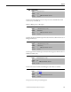
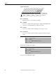
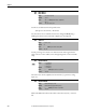
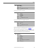
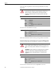
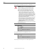
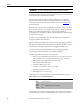
Table Of Contents
- Front Cover
- Important User Information
- Summary of Changes
- Table of Contents
- Introduction
- About the Drive
- Identifying the Drive by Cabinet Assembly ID Number
- LiquiFlo 2.0 Drive Component Locations
- Identifying the Power Module by Model Number
- AC Line I/O Board Description (Frame 3 Only)
- Standard I/O Board Description (Frame 3 Only)
- Combined I/O Board Description (Frame 4 Only)
- DPI Communication Ports
- Optional Equipment
- Planning the Installation
- Mounting The Power Module and Grounding the Drive
- Installing Input and Output Power Wiring
- Completing the Installation
- Using the Start-up Routines
- Programming Basics
- Parameter Descriptions
- Troubleshooting the Drive
- Verify that the DC Bus Capacitors are Discharged Before Servicing the Drive
- Determining Drive Status Using the Status LEDs
- About Alarms
- About Faults
- Diagnostic Parameters
- Common Symptoms and Corrective Actions
- Replacement Parts
- Board Replacement, Firmware Setup Procedures
- Troubleshooting the Drive Using the OIM
- Checking the Power Modules with Input Power Off
- Technical Specifications
- Using the OIM
- Installing and Removing the OIM
- Display Description
- OIM Menu Structure
- Powering Up and Adjusting the OIM
- Selecting a Device in the System
- Using the OIM to Program the Drive
- Monitoring the Drive Using the Process Display Screen on the OIM
- Displaying and Changing the OIM Reference
- Customizing the Process Display Screen
- Customizing the Function Keys
- Controlling the Drive From the OIM
- LiquiFlo 2.0 Drive Frame 3 Wiring Diagrams
- LiquiFlo 2.0 Drive Frame 4 Wiring Diagrams
- Index
- Back Cover

102 Rockwell Automation Publication D2-3518-3 - May 2013
Chapter 9
Figure 42 - PI Status (134)
Bit 0 – PI Enabled
• Indicates whether or not the PI loop is enabled.
Bit 1 – PI Hold
• Is set to 1 to indicate when a digital input is configured for PI Hold and is
turned on, or the PI Hold bit is set in PI Control (125).
Bit 2 – PI Reset
• Is set to 1 to indicate when the PI Integrator is being reset to zero.
Bit 3 – PI InLimit
• Is set to 1 to indicate when the PI output equals positive limit or negative
limit.
Present value of the PI reference signal.
Present value of the PI feedback signal.
135 PI Ref Meter
Range: -/+100.00% [0.01%]
Default: Read Only
Access: 1 Path: Speed Command > Process PI
See also: 124...138
136 PI Fdback Meter
Range: -/+100.00% [0.01%]
Default: Read Only
Access: 1 Path: Speed Command > Process PI
See also: 124...138
0000xxxxxxxxxxxx
0011234567891112131415
1=Condition True
0=Condition False
x =Reserved
Bit #
PI Enabled
PI Hold
PI Reset
PI InLimit
Nibble 1Nibble 2Nibble 3Nibble 4