
Owner's manual
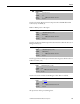
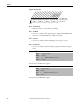
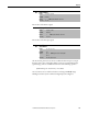
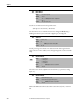
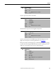
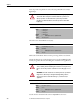
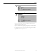
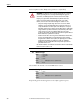
Table Of Contents
- Front Cover
- Important User Information
- Summary of Changes
- Table of Contents
- Introduction
- About the Drive
- Identifying the Drive by Cabinet Assembly ID Number
- LiquiFlo 2.0 Drive Component Locations
- Identifying the Power Module by Model Number
- AC Line I/O Board Description (Frame 3 Only)
- Standard I/O Board Description (Frame 3 Only)
- Combined I/O Board Description (Frame 4 Only)
- DPI Communication Ports
- Optional Equipment
- Planning the Installation
- Mounting The Power Module and Grounding the Drive
- Installing Input and Output Power Wiring
- Completing the Installation
- Using the Start-up Routines
- Programming Basics
- Parameter Descriptions
- Troubleshooting the Drive
- Verify that the DC Bus Capacitors are Discharged Before Servicing the Drive
- Determining Drive Status Using the Status LEDs
- About Alarms
- About Faults
- Diagnostic Parameters
- Common Symptoms and Corrective Actions
- Replacement Parts
- Board Replacement, Firmware Setup Procedures
- Troubleshooting the Drive Using the OIM
- Checking the Power Modules with Input Power Off
- Technical Specifications
- Using the OIM
- Installing and Removing the OIM
- Display Description
- OIM Menu Structure
- Powering Up and Adjusting the OIM
- Selecting a Device in the System
- Using the OIM to Program the Drive
- Monitoring the Drive Using the Process Display Screen on the OIM
- Displaying and Changing the OIM Reference
- Customizing the Process Display Screen
- Customizing the Function Keys
- Controlling the Drive From the OIM
- LiquiFlo 2.0 Drive Frame 3 Wiring Diagrams
- LiquiFlo 2.0 Drive Frame 4 Wiring Diagrams
- Index
- Back Cover

Rockwell Automation Publication D2-3518-3 - May 2013 101
Chapter 9
Sets the value for the PI proportional component when the PI Hold bit of PI
Control (125) = Enabled (1).
PI Error x PI Prop Gain = PI Output
Sets the lower limit of the PI output. This value must be less than the value set in
PI Upper Limit (132).
Sets the upper limit of the PI output. This value must be greater than the value set
in PI Lower Limit (131).
Sets the value used to load into the PI Integrator when PI is not enabled.
The present state of the process PI regulator.
130 PI Prop Gain
Range: 0.00...100.00 [0.01]
Default: 1.00
Access: 1 Path: Speed Command > Process PI
See also: 124...138
131 PI Lower Limit
Range: -/+Maximum Frequency [0.1 Hz]
Default: -Maximum Freq
Access: 1 Path: Speed Command > Process PI
See also: 124...138
132 PI Upper Limit
Range: -/+Maximum Frequency [0.1 Hz]
Default: +Maximum Freq
Access: 1 Path: Speed Command > Process PI
See also: 124...138
133 PI Preload
Range: -/+Maximum Frequency [0.1 Hz]
Default: 0.0 Hz
Access: 1 Path: Speed Command > Process PI
See also: 124...138
134 PI Status
Range: See Figure 42
Default: Read Only
Access: 1 Path: Speed Command > Process PI
See also: 124...138